61
DISASSEMBLY PROCEDURE
PHOTOS
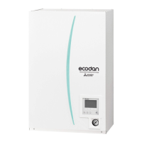
Photo 6-1
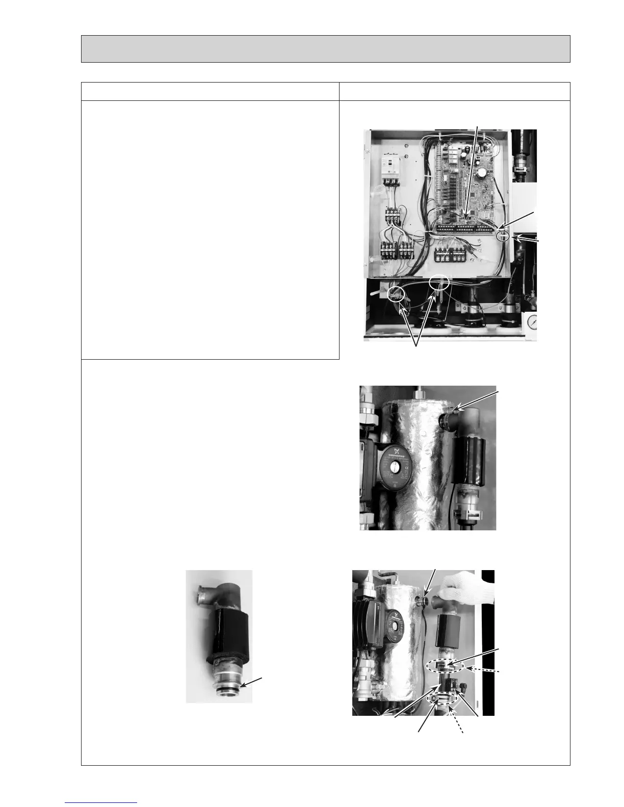
Photo 6-4
O-ring
6. How to remove the flow sensor
(1)Removethefrontpanel.(RefertoProcedure1.)
(2)DisconnecttheCN1Aconnectoronthecontrollerboard.
(Photo6-1)
(3)Releasetheflowsensorleadwirefromthecableclamp,
the2cablestrapsandfeedtheleadwireoutthecontrol
boxwithoutputtingstrainontheCN1Aconnector.
(Photo6-1)
(4)
Swingthecontrolboxtothefront.(RefertoProcedure4.)
(5)Removetheelbowjointbydetachingthedifferent
diameterquickconnection.(Photo6-2)
• Refertopage70forhowtoattachanddetachthe
different diameter quick connection.
(6)Removetheflowsensorbydetachingthesamediameter
quickconnection.(Photo6-3)
•
Whenreinstallingthesamediameterquickconnection,
useanewO-ring.(Photo6-4)
• ApplygreaseontheO-ringusingaplasticbag,etc.
(RefertoPhoto14-4onpage70.)
• Settheflowsensorintheorientationofthearrow
printedontheflowsensorandinthewaythatthe
sensorpartfacestothefront.(Photo6-3)
Cable
clamp
Leadwire
Same diameter
quick connection
O-ring
Sensor part
CN1A
connector
Photo 6-2
Photo 6-3
Flowsensor
Different diameter
quick connection
Same diameter
quick connection
O-ring
Cable strap
O-ring
 Loading...