209
PRECAUTIONS FOR MAINTENANCE AND INSPECTION
6
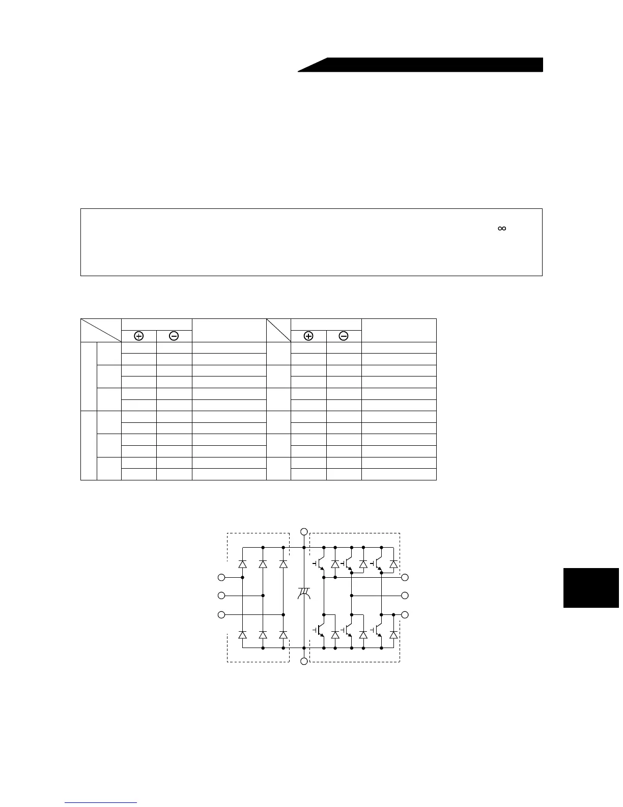
Checking the inverter and converter modules
<Preparation>
(1) Disconnect the external power supply cables (R, S, T <L1, L2, L3>) and motor cables (U, V, W).
(2) Prepare a tester. (Use 100
Ω range.)
<Checking method>
Change the polarity of the tester alternately at the inverter terminals R, S, T, U, V, W, P and N <L1, L2, L3, U,
V, W, + and ->, and check for continuity.
<Module device numbers and terminals to be checked>
(Assumes the use of an analog meter.)
Note: 1. Before measurement, check that the smoothing capacitor is discharged.
2. At the time of discontinuity, due to the smothing capacitor, the tester may not indicate . At the
time of continuity, the measured value is several to several ten's-of ohms depending on the
module type, circuit tester type, etc. If all measured values are almost the same, the modules are
without fault.
Tester P olarity
Measured Value
Tester Polarity
Measured Value
Converter module
D1
R <L
1> P <+> Discontinuity
D4
R <L1> N <-> Continuity
P <+> R <L
1> Continuity N <-> R <L1> Discontinuity
D2
S <L
2> P <+> Discontinuity
D5
S <L2> N <-> Continuity
P <+> S <L
2> Continuity N <-> S <L2> Discontinuity
D3
T <L
3> P <+> Discontinuity
D6
T <L3> N <-> Continuity
P <+> T <L
3> Continuity N <-> T <L3> Discontinuity
Inverter module
TR1
U P <+> Discontinuity
TR4
U N <-> Continuity
P <+> U Continuity N <-> U Discontinuity
TR3
V P <+> Discontinuity
TR6
V N <-> Continuity
P <+> V Continuity N <-> V Discontinuity
TR5
W P <+> Discontinuity
TR2
W N <-> Continuity
P <+> W Continuity N <-> W Discontinuity
D1 D2 D3
D4 D5 D6
TR1 TR3 TR5
TR4 TR6 TR2
U
V
W
C
Inverter moduleConverter module
R
〈
L
1
〉
S
〈
L
2
〉
T
〈
L
3
〉
P
〈
+
〉
N
〈
–
〉
 Loading...