20
INSTALLATION AND WIRING
(5) Connecting the control circuit to a power supply separately from the main circuit
If the magnetic contactor (MC) on the inverter power supply side is opened when the protective circuit is
operated, the inverter control circuit power is lost and the alarm output signal cannot be kept on. To keep the
alarm signal, terminals R1 and S1 are available. In this case, connect the power supply terminals R1 and S1
<L
11 and L21> of the control circuit to the primary side of the MC.
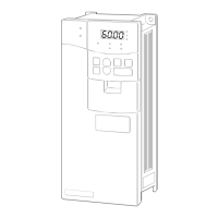
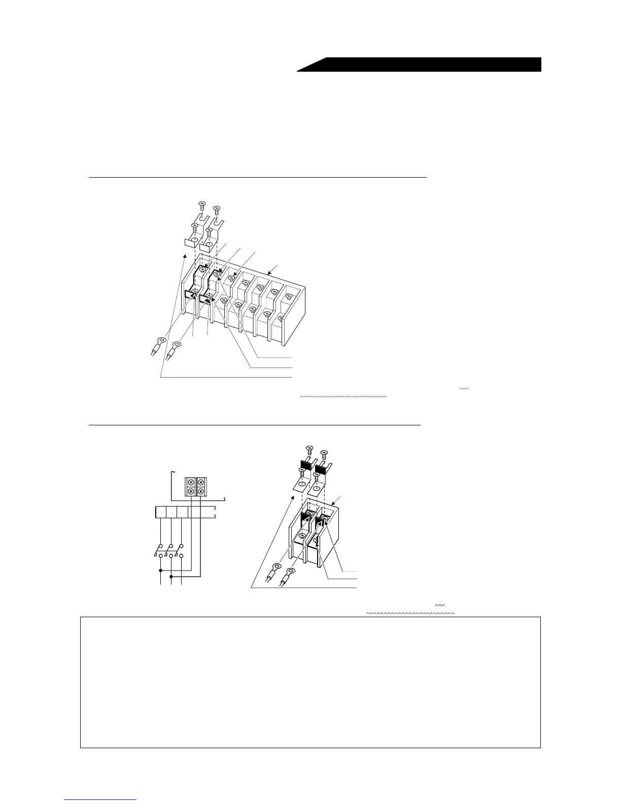
• Model FR-A520-0.4K to 3.7K-NA, FR-A540-0.4K to 3.7K-NA/-EC
<Connection procedure>
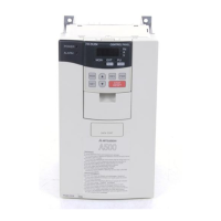
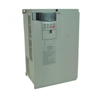
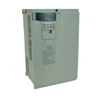
• Model FR-A520-5.5K to 55K-NA, FR-A540-5.5K to 55K-NA/-EC
<Connection procedure>
Note: 1. When the main circuit power (R, S, T) <L
1 L2, L3> is on, do not switch off the control power
(terminals R1, S1 <L
11, L21>). Otherwise the inverter may be damaged.
2. When using a separate power supply, the jumpers across R-R1 and S-S1 <L
1-L11 and L2-L21>
must be removed. Otherwise the inverter may be damaged.
3. For a different power supply system, which takes the power of the control circuit from other than
the primary side of the MC, the voltage should be equal to the main circuit voltage.
4. For the FR-A520-5.5K to 55K, FR-A540-5.5K to 55K, the power supply cables must not be
connected to the lower terminals. If connected, the inverter may be damaged.
5. Supplying power to only terminals R1 <L
11> and S1 <L21> and entering the start signal will result
in an error display (E.OC1).
Terminal block for main circuit
1) Loosen the upper screws
2) Remove the lower screws.
3) Remove the jumpers.
R
<L
1>
S
<L
2>
T
<L
3>
R1
<L
11>
S1
<L
21>
4) Connect the separate power supply cables for control circuit to the
lower terminals (R1, S1 L
11
, L
21
).
MC
Power supply terminal
block for control circuit
Main power supply
Power supply terminal
block for control circuit
R
〈
L
1
〉
S
〈
L
2
〉
T
〈
L
3
〉
R1
〈
L
11
〉
S1
〈
L
21
〉
1) Loosen the upper screws.
2) Remove the lower screws.
3) Pull out and remove the jumper.
4) Connect the separate power supply
cables for control circuit to the
upper terminals (R1, S1
〈
L
11
, L
21
〉
). (Note 4)
 Loading...