213
FX3G/FX3U/FX3UC Series Programmable Controllers
Programming Manual - Basic & Applied Instruction Edition
7 Basic Instruction
7.13 SET, RST
1
Introduction
2
Overview
3
Instruction
List
4
Devices
in Detail
5
Specified the
Device &
Constant
6
Before
Programming
7
Basic
Instruction
8
FNC00-FNC09
Program Flow
9
FNC10-FNC19
Move & Compare
10
FNC20-FNC29
Arith. & Logic
Operation
7.13 SET, RST
Outline
1) Setting a bit device (SET instruction (set bit device latch ON))
When the command input turns ON, SET instruction sets to ON an output relay (Y), auxiliary relay (M), state relay
(S) and bit specification (D.b) of word device.
Even if the command input turns OFF after that, the device which was set to ON by SET instruction remains ON.
2) Resetting a bit device (RST instruction (reset bit device OFF))
RST instruction resets an output relay (Y), auxiliary relay (M), state relay (S), Timer (T), counter (C) or bit
specification (D.b) of a word device.
Use the RST instruction to reset (set to OFF) a device which was set to ON by SET instruction.
3) Clearing the present value of a word device (RST instruction reset bit device OFF))
RST instruction clears the current value of a timer (T), counter (C), data register (D), extension register (R) or
index register (V)(Z).
RST instruction can be used to clear to "0" the contents of a data register (D) or index register (V)(Z). (The same
result can be obtained by MOV instruction which transfers the constant K0.)
RST instruction can be used also to reset the current value and return the contact of retentive type timers T246 to
T255.
SET and RST instructions can be used for the same device as many times as necessary in an arbitrary order.
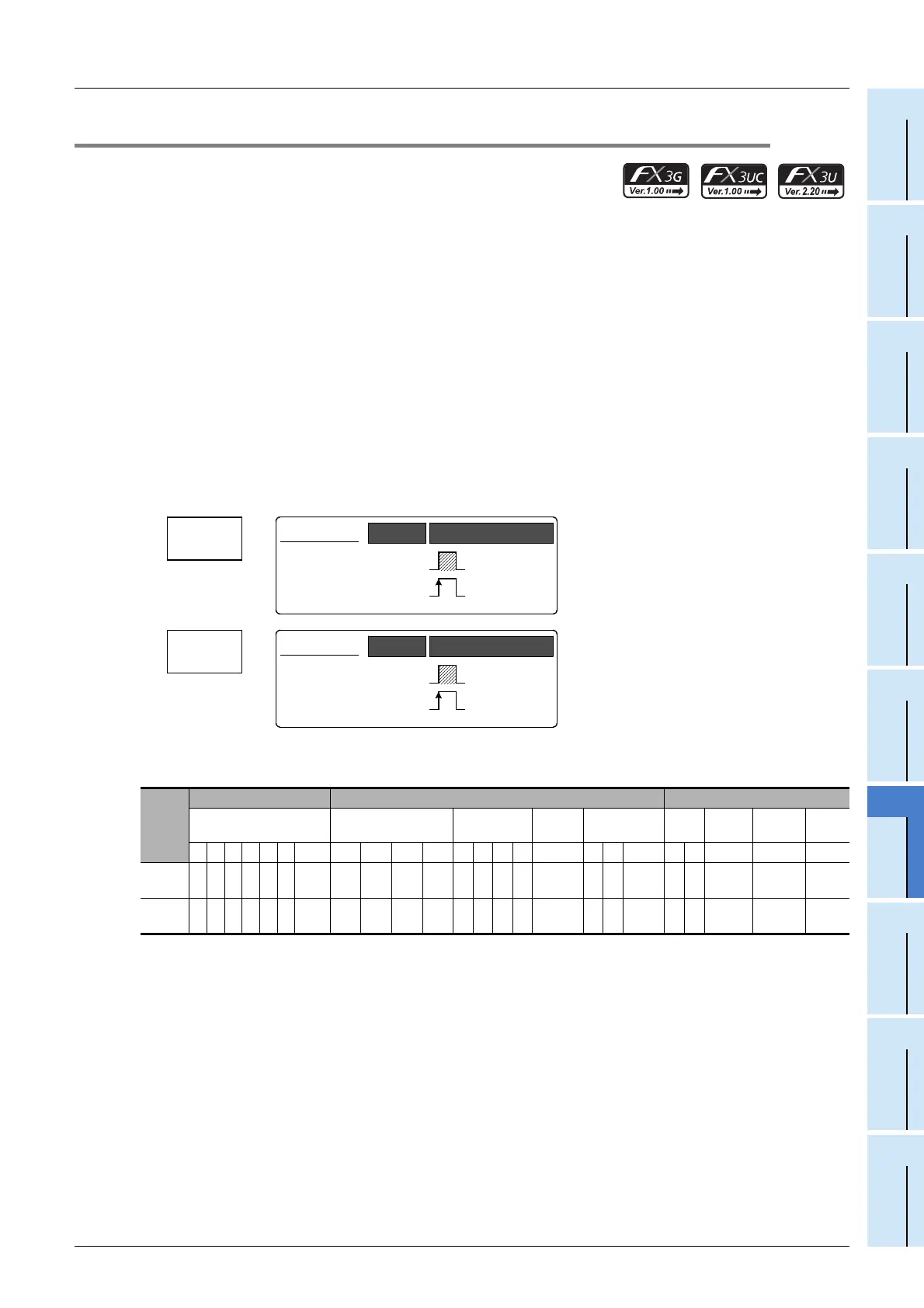
1. Instruction format
→ For the number of instruction steps, refer to Section 7.15.
2. Applicable devices
S1: Special auxiliary relays (M) and 32-bit counters (C) cannot be indexed with index registers (V and Z).
S2: State relays (S) cannot be indexed with index registers (V and Z).
S3: "D.b" is available only in FX
3U and FX3UC PLCs. However, index modifiers (V and Z) are not available.
S4: This function is supported only in FX
3U/FX3UC PLCs.
Instruc-
tion
Bit Devices Word Devices Others
System User Digit Specification System User
Special
Unit
Index
Con-
stant
Real
Number
Charac-
ter String
Pointer
XYMTCSD.b KnX KnY KnM KnS T C D R U\G V Z Modify K H E ""P
SET 3
S
1
S
2
S3 S4
RST 3
S
1
3
S
1
S
2
S3
S
2
S
2
S
2
S
2
S
2
S
2
S4
SET
SET
Basic Instruction
SET
−
Continuous
Operation
Pulse (Single)
Operation
Mnemonic Operation Condition
RST
Reset
Basic Instruction
RST
−
Continuous
Operation
Pulse (Single)
Operation
Mnemonic Operation Condition

 Loading...