695
FX3G/
FX
3U
/FX
3UC
Series Programmable Controllers
Programming Manual - Basic & Applied Instruction Edition
30 External Device Communication (Inverter Communication) – FNC270 to FNC275
30.5 FNC274 – IVBWR / Inverter Parameter Block Write
21
FNC160-FNC169
Real Time Clock
Control
22
FNC170-FNC179
External Device
23
FNC180
Alternate
Instructions
24
FNC181-FNC189
Others
25
FNC190-FNC199
Block Data
Operation
26
FNC200-FNC209
Character String
Control
27
FNC210-FNC219
Data
Operation 3
28
FNC220-FNC249
Data
Comparison
29
FNC250-FNC269
Data Table
Operation
30
FNC270-FNC275
Ex-Device
Inverter Comms
30.5 FNC274 – IVBWR / Inverter Parameter Block Write
Outline
This instruction writes parameters of an inverter at one time using the computer link operation function of the inverter.
→ For detailed explanation of the instruction, refer to the Data Communication Edition manual.
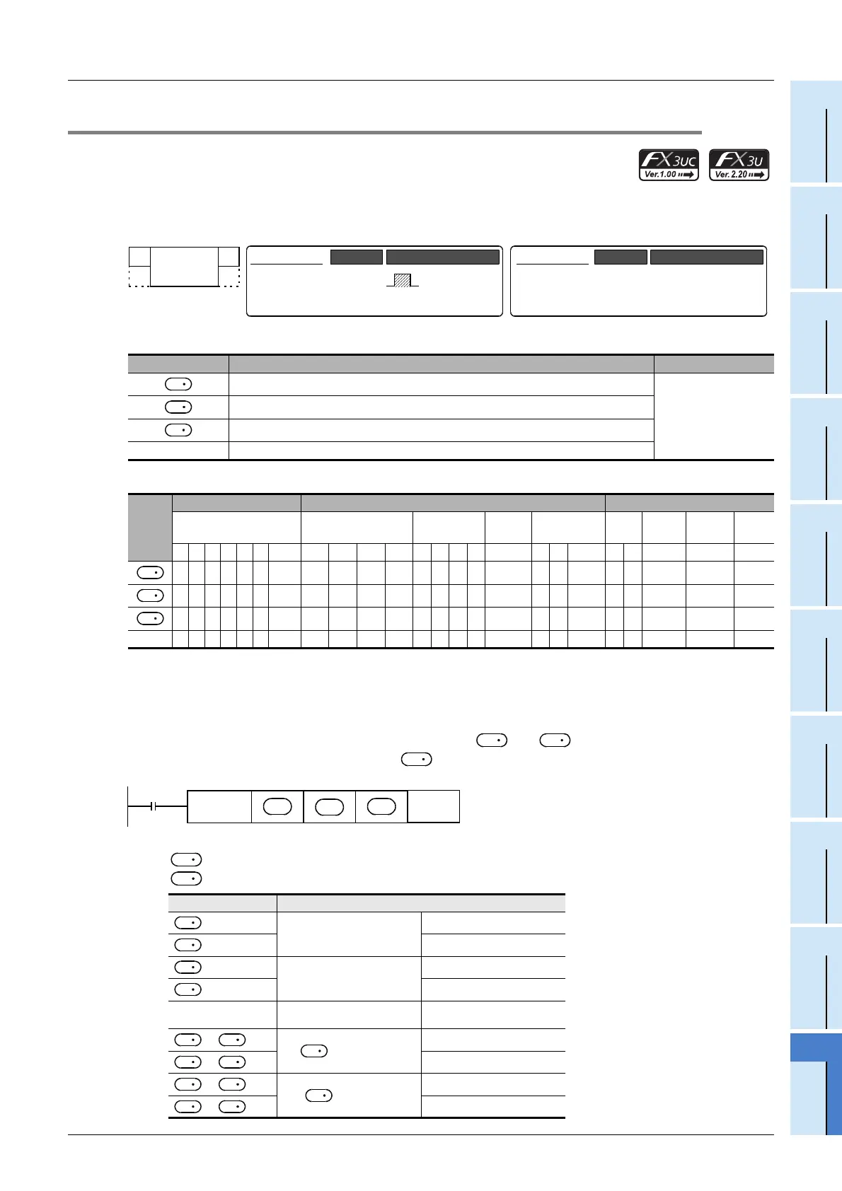
1. Instruction format
2. Set data
3. Applicable devices
Explanation of function and operation
→ For detailed explanation of the instruction, refer to the Data Communication Edition manual.
1. 16-bit operation (IVBWR)
A data table
*1
(parameter numbers and set values) specified in and is written to an inverter connected to
a communication port n whose station number is all at once.
*1. The table below shows the data table format.
: Number of parameters to be written
: Head device number of data table
Operand Type Description Data Type
Station number of an inverter (K0 to K31)
16-bit binary
Number of parameters in an inverter to be written at one time
Head device number of a parameter table to be written to an inverter
n Used channel (K1: ch 1, K2: ch 2)
Oper-
and
Type
Bit Devices Word Devices Others
System User Digit Specification System User
Special
Unit
Index
Con-
stant
Real
Number
Charac-
ter String
Pointer
XYMTCSD
.b KnX KnY KnM KnS T C D R
U\G
V Z Modify K H E "
"P
33 3 3 33
33 3 3 33
33 3 3
n 33
Device Parameter numbers to be written and set values
1st parameter
Parameter number
+1
Set value
+2
2nd parameter
Parameter number
+3
Set value
...
...
...
+2 -4
“ -1”th parameter
Parameter number
+2 -3
Set value
+2 -2
“ ”th parameter
Parameter number
+2 -1
Set value
FNC 274
IVBWR
Mnemonic Operation Condition
16-bit Instruction
9 steps
IVBWR
Mnemonic Operation Condition
Continuous
Operation
32-bit Instruction
⎯
⎯⎯
S
1
S
2
S
3
S
1
S
2
S
3
S
2
S
3
S
1
FNC274
IVBWR
S
1
S
2
S3
n
Command
input
S
2
S
3
S
3
S
3
S
3
S
3
S
3
S
2
S
2
S
3
S
2
S
3
S
2
S
2
S
3
S
2

 Loading...