7 Applied Instructions
7.6 High Speed Processing
299
FXCPU Structured Programming Manual
(Basic & Applied Instruction)
1
Outline
2
Instruction List
3
Configuration of
Instruction
4
How to Read
Explanation of
Instructions
5
Basic Instruction
6
Step Ladder
Instructions
7
Applied
Instructions
8
Interrupt Function
and Pulse Catch
Function
A
Relationships
between devices
and addresses
Comparison table
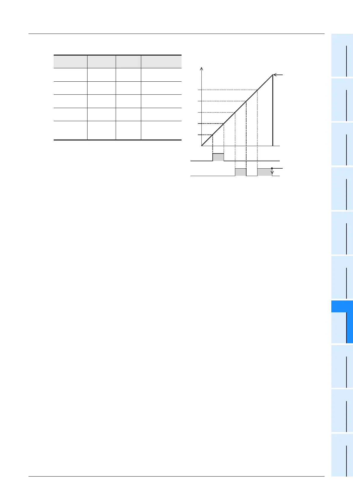
1) When this instruction is executed, the top table
in the data table is set as the comparison
target data.
2) When the current value of the high speed
counter C251 is equivalent to the comparison
target data table, the output (Y) number
specified in the comparison data table is set or
reset.
This output processing is directly executed without regard to completion of output refresh by END
instruction.
3) "1" is added to the current value of the table counter D8130.
4) The comparison target data table is transferred to the next table.
5) The step 2) and 3) are repeated until the current value of the table counter D8130 becomes "4".
When the current value becomes "4", the program execution returns to the step 1), and the table counter
D8130 is reset to "0".
At this time, the complete flag M8131 turns ON.
6) When the command contact is set to OFF, execution of the instruction is stopped and the table counter
D8130 is reset to "0".
Cautions
1. Limitation in the number of DHSZ instruction
This instruction can be programmed only once in a program.
With regard to the DHSCS, DHSCR, DHSZ and DHSCT instructions used for other purposes, a limited
number of instructions including the DHSZ instruction can be driven at one time.
2. When the command input is set to OFF in the middle of execution
Execution of the instruction is aborted, and the table counter D8130 is reset to K0.
However, outputs which have been set or reset remain in the current status.
3. Output start timing
After the DHSZ instruction is first executed, creation of the table is completed by END instruction. After that,
the DHSZ instruction becomes valid.
Accordingly, the output is activated from the second scan.
4. Current value of a high speed counter
Be sure to execute the DHSZ instruction from a point where the current value of the high speed counter
(regarded as the operation target) is smaller than the value in the first line in the comparison table.
Comparison
data
Output (Y)
number
SET/RST Table counter
D201, D200
K123
D 202
H10
D 203
K1
0
↓
D205, D204
K234
D 206
H10
D 207
K0
1
↓
D209, D208
K345
D 210
H11
D 211
K1
2
↓
D213, D212
K456
D 214
H11
D 215
K0
3
↓
D217, D216
K567
D 218
H11
D 219
K1
4
↓
Repeated from "0"
567
456
345
234
123
Y010
Y011
Current value
of C251
A program
to reset the
counter is
required.
A program
to reset the
output is
required.

 Loading...


