660
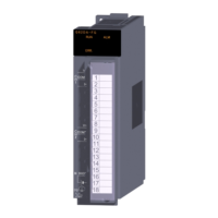
(11)Q68TD-G (-H01/-H02) type channel isolated thermocouple input module and
Q68RD3-G type channel isolated RTD input module
Wiring as shown below is required.
• Use a shielded cable for connection between the external device connector and relay terminal block, and
ground the shield section of the cable to the control panel. Keep the wiring length to 3m or less.
• Use a shielded cable for external wiring, and ground the shield section of the cable to the control panel using
the AD75CK cable clamp (Mitsubishi). (Ground the shield section within 20 to 30cm from the relay terminal
block.)
• Before handling the relay terminal block, touch a grounded metal object to discharge the static electricity
from the human body.
In a control panel
20 to 30cm
AD75CK
Q68TD-G-H02(H01)
Relay
terminal
block
A6CON4
Strip off the outer
sheath

 Loading...


