P
C.
c
..
c
i..
C
L-
i
..-
P
c.
L
..
P
C
2.
SYSTEM
CONHGURATION
/MELSEC-A
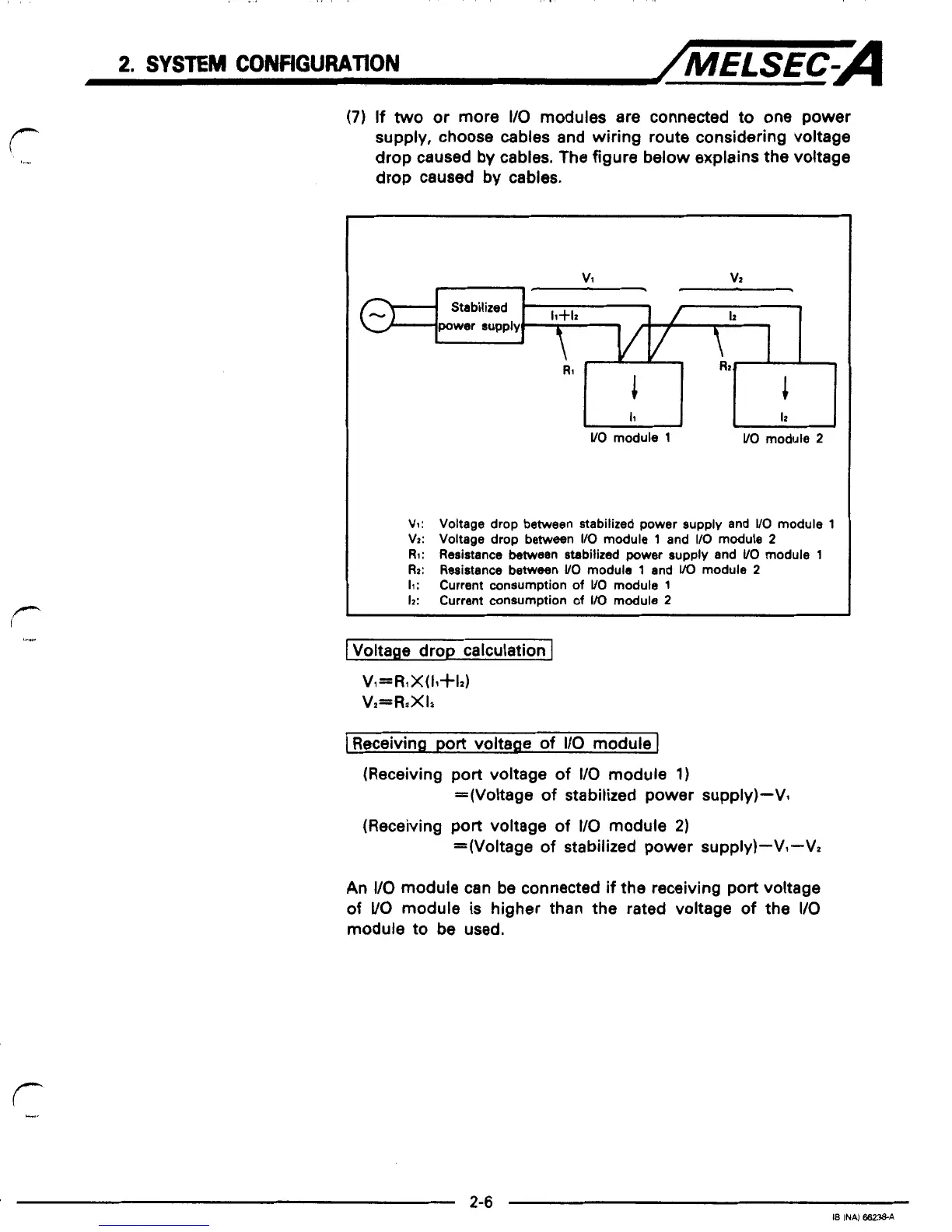
(7)
If
two
or more
I/O
modules are connected to one power
supply, choose cables and wiring route considering voltage
drop caused by cables. The figure below explains the voltage
drop caused by cables.
v1
vz
+
Stabilized
-
h
Rz
I
i
I1
I2
UO
module
1
VO
module
2
V1: Voltage drop between stabilized power supply and
VO
module
1
VZ:
Voltage drop between
I/O
module
1
and
I10
module
2
RI:
Resistance between stabilized
power
supply and
UO
module
1
Rz:
Resistance between
UO
module
1
and
VO
module
2
11:
Current consumption
of
VO
module
1
12:
Current consumption
of
VO
module
2
1
Voltage drop calculation
J
V,=R1X(11+12)
Vz=RzXIz
I
Receiving
port
voltage
of
I/O
module
I
(Receiving
port
voltage
of
I10
module
1)
(Receiving port voltage
of
VO
module
2)
=(Voltage
of
stabilized power supply)-Vl
=(Voltage
of
stabilized power supply)-V1-V2
An
I/O
module can be connected
if
the receiving port voltage
of
VO
module is higher than the rated voltage
of
the
I/O
module to be used.
 Loading...


