2.
SYSTEM
CONFtGURATlON
/MELSEC-A
2.3
Systm
Equipment
tq
-
-'
I
In this
section,
the
VO
modules and peripheral devices which can
be used with the A2C are listed.
2.3.1
Modules
which
can
be
connected
to the
A2CCPU
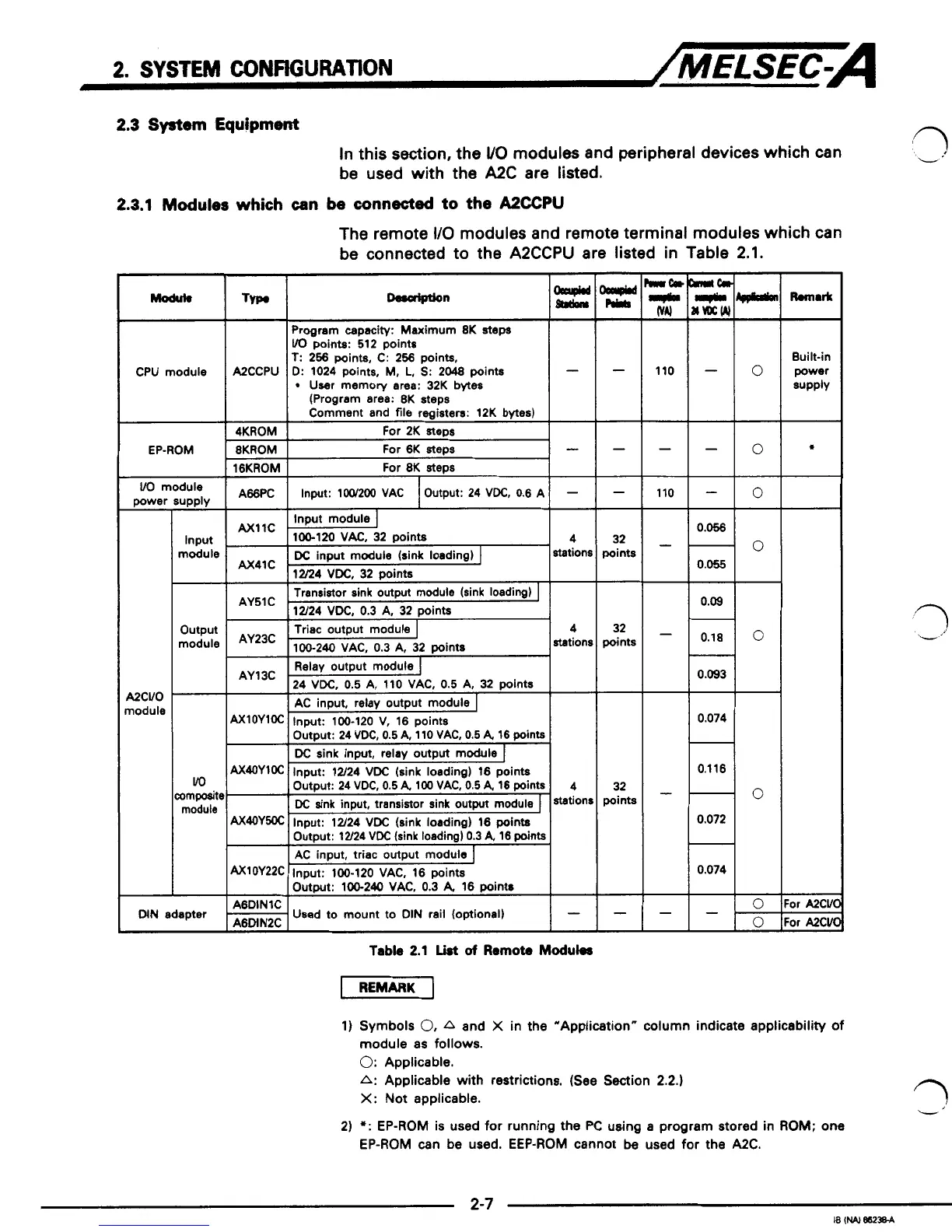
The remote
I/O
modules and remote terminal modules which can
be connected to the A2CCPU are listed in Table 2.1.
Typ.
I
Program capacity: Maximum
8K
steps
VO
points:
512
points
T:
256
points,
C: 256
points,
D:
1024
points,
M,
L,
S:
2048
points
User memory area:
32K
bytes
-
(Program area:
8K
steps
Comment and
file
registers:
12K
bytes)
For
2K
steps
-lo
CPU module
A2CCPU
4KROM
i
EP-ROM
-
-
110
8KROM
16KROM
For
6K
steps
For
8K
steps
-
A66PC
-
Output:
24
VDC,
0.6 A
Input:
1W200 VAC
1
VO
module
UPPlY
Input
module
power
UCVO
nodule
c
32
points
32
points
I
Transistor sink outmt module (sink loadimr)
I
I
I
12/24
VDC.
0.3
A. 32
ooints
I
output
module
vo
ompositc
module
AY23C
station!
AY13C
rl
0.093
I
AC
input,
relay
output module
0.074
0.1 16
-
0.072
-
0.074
32
points
0
n
-.
I
bd
I
Output:
100-240 VAC,
0.3
A,
16
points
-
I+
or
AXVl
'or
A2Cvl
-
A6DINlC
A6MN2C
Used
to
mount to
DIN
rail (optional)
-
DIN
adapter
Table
2.1
List
of
Remote
Maduks
1)
Symbols
0,
A
and
X
in the "Application" column indicate applicability
of
module as
follows.
0:
Applicable.
A:
Applicable with restrictions. (See Section
2.2.)
X:
Not applicable.
2)
*:
EP-ROM is used
for
running the
PC
using a program stored in
ROM;
one
EP-ROM can be used. EEP-ROM cannot
be
used
for
the
A2C.
 Loading...


