..
--
f“
c
I..
i,
P
C.
c
..
r-
L.
P
P
2.
SYSTEM
CONFIGURATION
/MELSEC.A
conversion
terminal
module
counter
Interface
module
1
0
AJWF-R2
F-
16NP
8
channels,
4
to
20
mA/O to
i10
V,
12-bit analog input
2
channels, binary
24
bits, 1/2
phase
input, reversible counter,
50
kpp
0.3
4
32
--
r”
points
0
0.15
No-protocol
0
0.20
x
ID
plate
X
Connecting module for
-
external devices
of
RS-
Bar code
4
32
-
23X
interface speci- reader
rtstions
points
fications
-
Used
for connecting
MELSEC-F 2
16
-
*l
-
A
series
PCs
to
the
A2C.
stations points
0
Used
for connecting the Mitsubishi
verters to the
AZC.
FR-2200
series
general-purpose in-
Conforms
to the
Mitwbishi
Standard
Protocol.
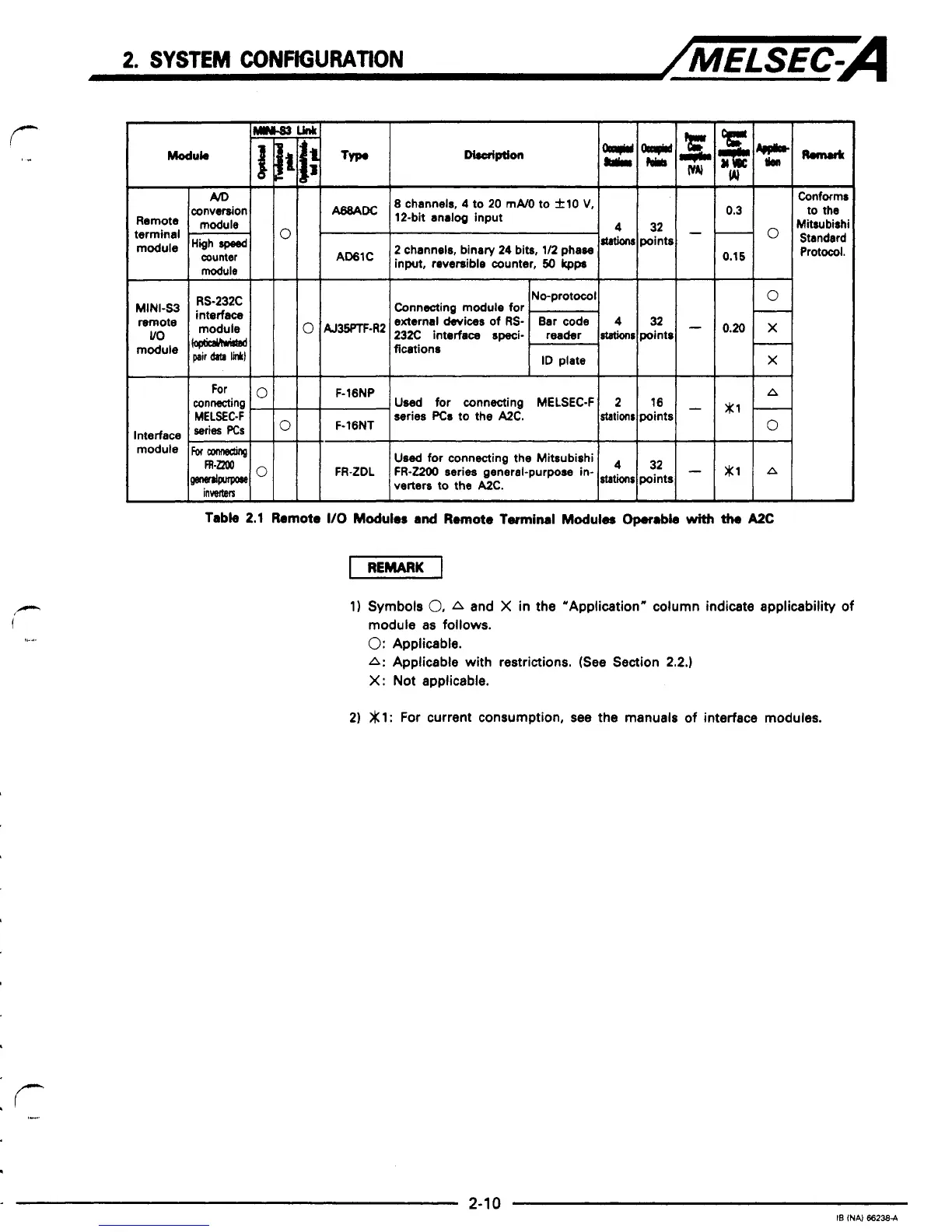
Table
2.1
Remote
I10
Modules
and
Remote
Twminal
Modules
Op.r.bk
with
the
AzC
1)
Symbols
0,
A
and
X
in the “Application“ column indicate applicability
of
module as
follows.
0:
Applicable.
A:
Applicable with restrictions. (See Section
2.2.)
X:
Not applicable.
2)
gl:
For
current consumption, see the manuals
of
interface modules.
 Loading...


