10
9
30
*1
32
32
33
34
B
30
30
35
A
Pa
11
8
27
19
16
20
18
17
21
37
3
7
13
29
36
32
34
32
4
25
5
23
6
7
24
15
14
7
12
26
3
10
29
9
30
32
32
34
34
32
B
31
A
31
32
33
Pa
11
4
25
8
27
7
19
5
15
13
16
23
20
14
6
7
24
18
17
*1
7
30
22
12
26
39
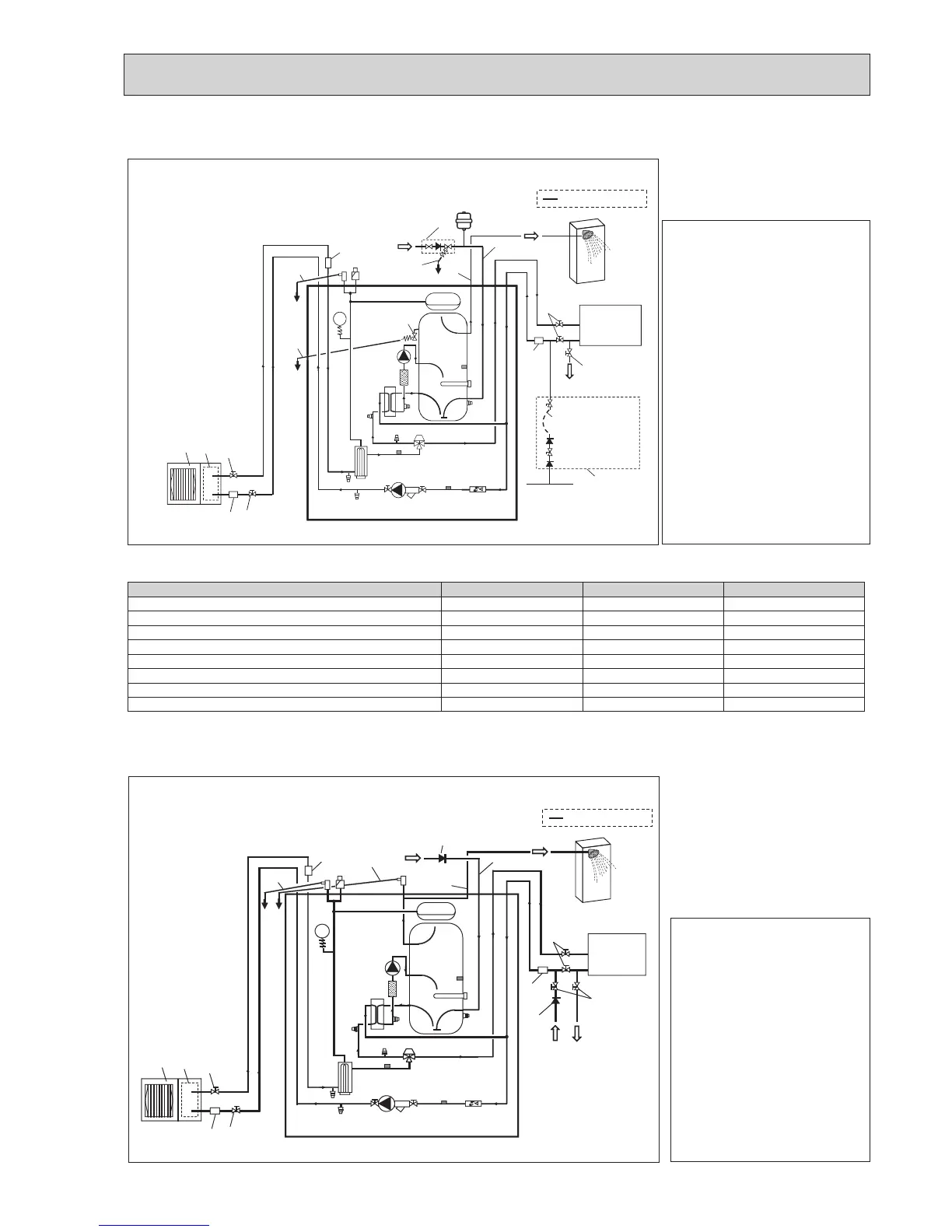
<EHPT20X-MHCW>(UKPackagedmodelsystem)<Example>
Notes:
•Toenabledrainingofthecylinderunitan
isolatingvalveshould be positioned on
boththeinlet and outlet pipework. No
valveshouldbe fittedbetweentheex-
pansion valve (item 35) and the cylinder
unit (safety matter).
•Besure to installastrainerontheinlet
pipeworktothecylinderunit.
•Suitabledrain pipework shouldbeat-
tached to all relief valves in accordance
withyourcountry’sregulations.
•Whenusingcomponentsmadefromdif-
ferentmetalsorconnectingpipesmade
ofdifferentmetalsinsulatethejointsto
preventanycorrosivereactiontaking
placewhichmaydamageanypipework.
•Fillingloop’sflexiblehosemustbere-
movedfollowingthe fillingprocedure.
Itemprovided with unitaslooseacces-
sory.
•Installthe inlet controlgroup(item35)
abovethelevel of theT&Preliefvalve
(item21).ThiswillensureDHWtank
willnotrequire drain-down to service/
maintaintheinletcontrolgroup.
Model name EHPT20X-MHCW EHST20C-MHCW EHST20D-MHCW
Maximumsupplypressuretothepressurereducingvalve 16 bar 16 bar 16 bar
Operatingpressure(Potableside) 3.5 bar 3.5 bar 3.5 bar
Expansionvesselchargesettingpressure(Potableside) 3.5 bar 3.5 bar 3.5 bar
Expansionvalvesettingpressure(Potableside) 6.0 bar 6.0 bar 6.0 bar
Immersionheaterspecication(Potableside)* 3000 W, 230 V 3000 W, 230 V 3000 W, 230 V
DHW tank capacity 200 L 200 L 200 L
Massoftheunitwhenfull 307kg 320kg 312kg
Maximumprimaryworkingpressure 2.5 bar 2.5 bar 2.5 bar
*EN60335/Type3000Wsinglephase230V50Hz,length460mm.
Use only Mitsubishi Electric service parts as a direct replacement.
<Table 8-1>
<EHPT20X-*M*C>(Packagedmodelsystem)
Notes:
•Toenabledrainingofthecylinder
unitanisolating valve should be po-
sitioned on both the inlet and outlet
pipework.
•Besuretoinstallastrainerontheinlet
pipeworktothecylinderunit.
•Suitabledrain pipework should be
attached to all relief valves in accord-
ancewithyourcountry’sregulations.
•Abackflowpreventiondevicemust
beinstalledon the cold watersupply
pipework(IEC61770)
•Whenusing components made from
differentmetalsorconnectingpipes
made of different metals insulate the
jointstopreventany corrosive reac-
tiontakingplacewhich may damage
thepipework.)
<Figure8-3>
<Figure8-4>
Cylinder unit
Drain
Drain
Drain
Drain
Coldwater
DHW
Local system
Mainwatersupply
Flexiblehose
(Temporary connection)
Cylinder unit
Drain
Drain
Coldwater
DHW
Local system
Water
supply
Water pipe
Water pipe
•Refer to <Table 4-1 and 4-2> for the part names.
*1Refertothefollowingsection[Localsystem].
 Loading...

