MANUAL TRANSMISSION (E-W) -
Output Shaft
22A-4-8
PWEE9508
E
May 1995Mitsubishi Motors Corporation
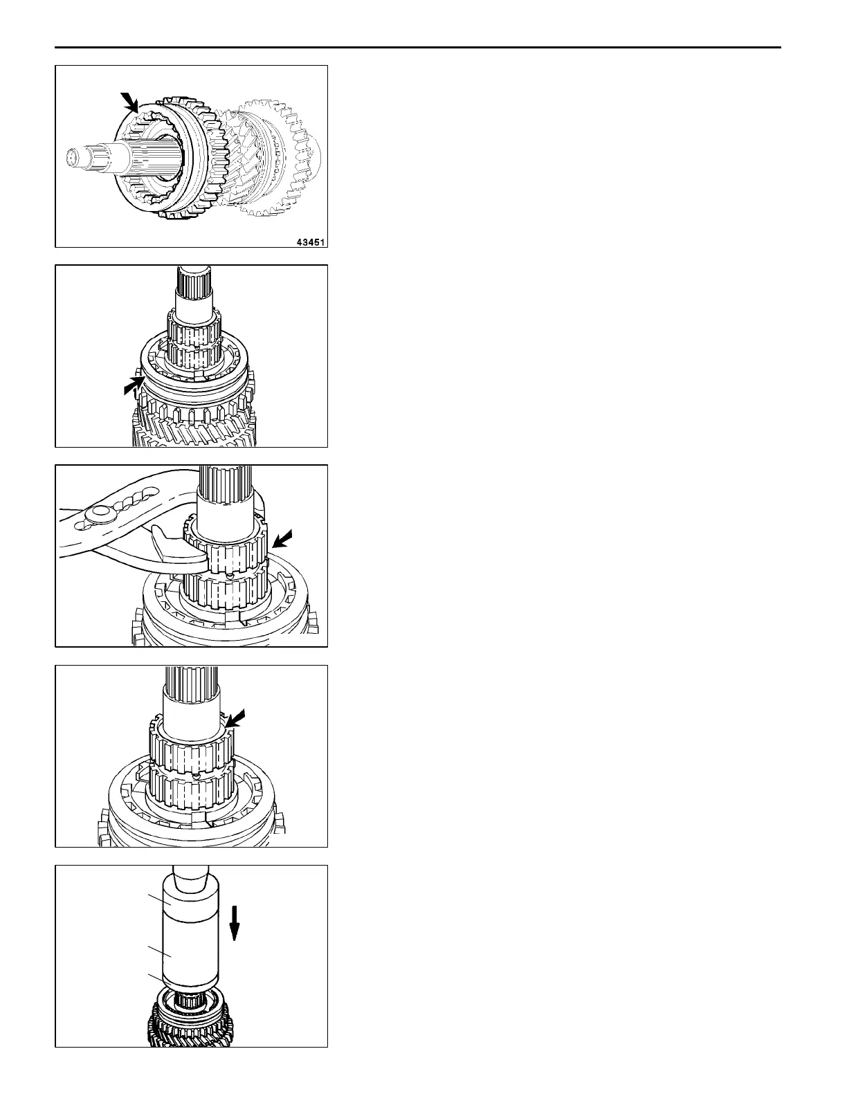
(4) Locate the hub together with the synchronizer sleeve
on the shaft with the teeth facing towards the gear wheels.
NOTE
Make sure that the lugs of the synchronizer ring engage
the recesses in the synchronizer sleeve.
"
L
A
3RD - 4TH GEAR SYNCHRONIZER HUB
INSTALLATION
Locate the hub together with the synchronizer sleeve, with
the groove for the shift fork facing up.
"
M
A
4TH GEAR WHEEL BEARING BUSH
INSTALLATION
(1) Locate the bearing bush so that the oil passages of the
bearing bush and the output shaft are opposed.
(2) Place the heated bearing bush, using a pair of gripping
pliers, over the output shaft on the synchronizer hub.
NOTE
Allow the bearing bush to cool and then lubricate copiously
with transmission fluid.
(3) Check that the bearing bush is flush with the mating face
of the output shaft and the shim. Bring the bearing bush
to the same height as the mating face.
(4) Place the output shaft under a press.
(5) Press the bearing bush down with drift installer cap
MD998812, installer - 100 MD998813, installer adapter
MD998819 until the drift abuts the mating face of the
shim.
RMT0058
RMT0038
RMT0039
AddedPWEE9508-BMitsubishi Motors Corporation
May 1996
E
RMT0040
MD998812
MD998813
MD998819
 Loading...