1.
PRECAUTIONS
Use
ttte
inverter within
the
permissible
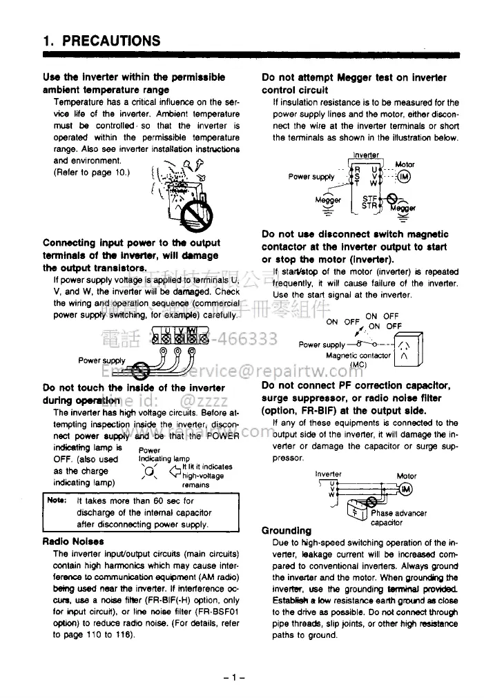
Do not attempt Megger test on inverter
ambient temperature range
control circuit
Temperature has a critical influence
on
the ser-
If
insulation reSiStanCe is to
be
measured for the
vice
life of
the
inverter. Ambient tempereture power supply lines and the motor, either discon-
must
be
controll%d.
so
that the inverter is
operated within the permissible temperature
nect the wire at the inverter terminals or short
the terminals
as
shown in the illustration below.
range. ~tso
see
inverter instakation
inst~tions
and environment.
(Refer
to
page 10.)
{
\.
'
:?-:A
4P
ic
Connecting input power to
Uw
output
twninals
of
Uw
inverter, will drmage
the
output
transistors.
If power supply vonage is
applied
to terminals
U,
V,
and W, the inverter will
be
damaged. Check
the wiring and operation sequence (commercial
power
supply
switching, for
example)
carefully.
Power
supply
a
Do
not touch
the
Inside
of
the inverter
during
opemtion
The inverter has hgh vokage circuits. Before at-
tempting inspection inside the inverter, discon-
nect power supply
and
be
that the POWER
imine
lamp
is
P~~~~
OFF.
(also used
iGGting
!amp
as
the
charge
;o:
+H
I#
it
indites
indicating lamp)
hlgh-voltage
remalns
HOW
It takes more than
60
sec
for
discharge
of
the internal capacitor
after disconnecting power supply.
Radio Noiws
The inverter input/ouput circuits (main circuits)
contain high hannonics which may
cause
inter-
ference
Lo
cnmmunicaticm equipment (AM radio)
b3ing
used
near
the
irrverter.
If
mteriarence
oc-
cum,
use
a
noise
fikr (FR-EIF(-H) option, only
foc
inprt
circuit), or line
noise
filter (FR-BSFO1
optron)
to
reduce radio noise. (For details, refer
to
page
110 to 116).
Inverter
-.
Do
not use disconnect switch magnetic
contactor at the inverter output to start
or
stop
the
motor (inverter).
If
starYstop of the motor (inverter)
is
repeated
frequently,
it
will
cause
failure of the inverter.
Use
the start slgnal at the inverter.
ON
OFF
ON
OFF
/,ON OF&
Power
supply
-.-
-
(
)
Magnetic
mntmor
A
(MC)
UJ
Do
not connect PF correction capacttor,
surge suppressor, or radio noise filter
(option, FR-BIF) at the output side.
If any of these equipments
is
connected to the
output side
of
the inverter,
it
will damage
the
in-
verter or damage the capacitor or surge
sup-
pressor.
Inverter
%jiE!Oml
capadtor
Grounding
Due to hgh-speed switching operation
of
the
in-
verter, leakage current will
be
increased
corn
pared to conventional inverters. Always ground
the inverter and
the
motor. When ~~ounding
fhe
invertsr.
use
the
grounding
twmiml
provided
EstaMisk
e
low
resistawe earlh gmd
8s
close
to
the drive
as
possible.
Do
not
connect through
pipe threads, slip joints, or other high
resblsnce
paths
to
ground.

 Loading...