FX3U Series Programmable Controllers
User’s Manual - Hardware Edition
192
10 Input Wiring Procedures (Input Interruption and Pulse Catch)
10.2 24V DC Input Type (Common to Sink/Source Input)
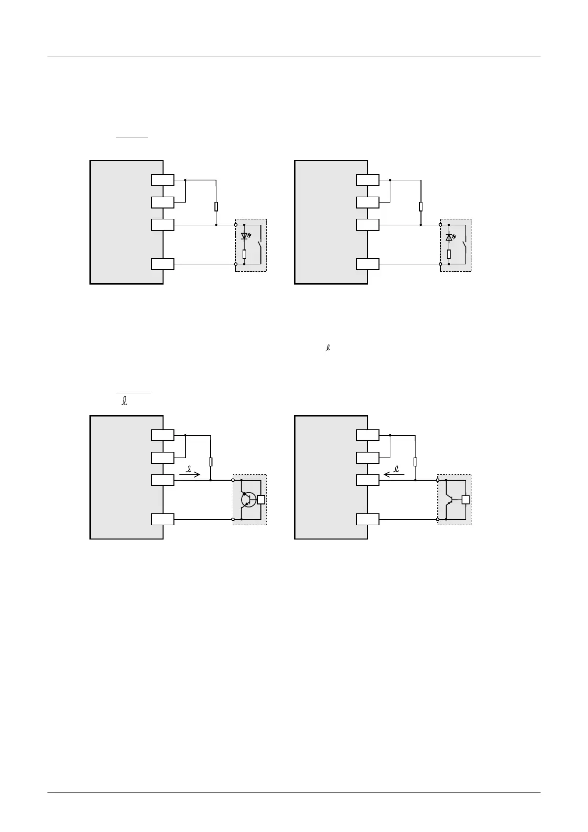
3. In case of input device with built-in parallel resistance
Use a device with a parallel resistance, Rp, of 15kΩ or more.
If the resistance is less than 15kΩ, connect a bleeder resistance, Rb, obtained by the following formula as
shown in the following figure.
4. In case of 2-wire proximity switch
Use a two-wire proximity switch whose leakage current, I , is 1.5 mA or less when the switch is off.
When the current is 1.5 mA or more, connect a bleeder resistance, Rb, determined by the following formula
as shown in the following figure.
Rb
4Rp
15-Rp
(k
Ω
)
≤
PLC
(source input)
X
24V
Rp
Rb
PLC
(sink input)
X
0V
Rp
Bleeder
resistance
Rb
15k or
more
*1
24V
S/S S/S
0V
*1 In case of a type only for sink input,
connect the device to the COM terminal.
Bleeder
resistance
15k or
more
Rb
6
I -1.5
(k
Ω
)
≤
PLC
(source input)
X
24V
Rb
I
PLC
(sink input)
X
0V
Rb
I
2-wire
proximity
sensor
*1
24V
S/S S/S
0V
*1 In case of a type only for sink input,
connect the device to the COM terminal.
Bleeder
resistance
Bleeder
resistance
2-wire
proximity
sensor

 Loading...


