FX3U Series Programmable Controllers
User’s Manual - Hardware Edition
241
12 Output Wiring Procedures
12.3 External Wiring of Transistor Output (Sink/Source) Type
11
High-Speed
Counters
12
Output Wiring
13
Wiring for
Various Uses
14
Test Run,
Maintenance,
Troubleshooting
15
IInput/Output
Powered
Extension Units
16
Input/Output
Extension
Blocks
17
Extension
Power Supply
Unit
18
Other Extension
Units and
Options
19
Display Module
20
Terminal Block
12.3.4 External wiring precautions
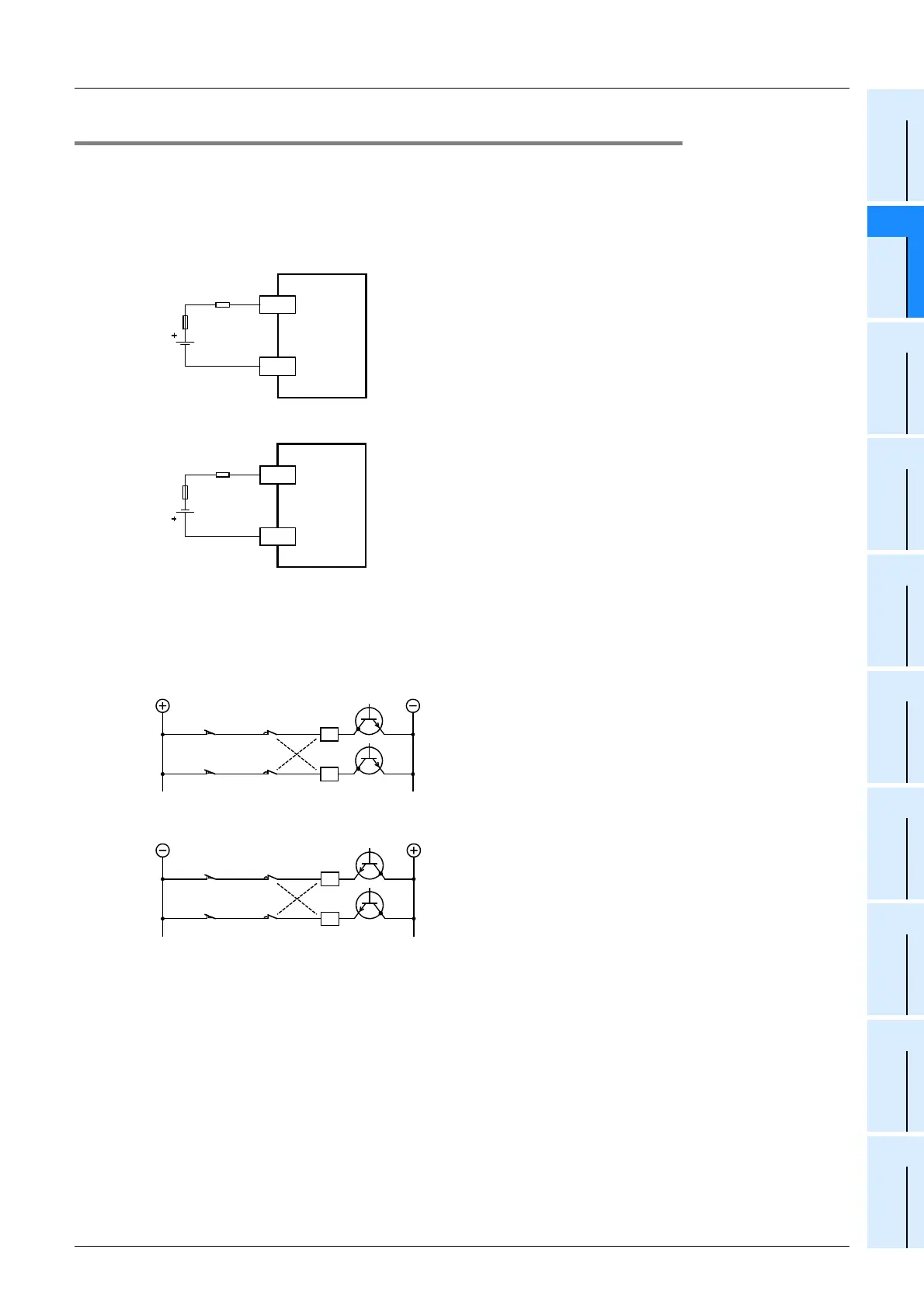
1. Protection circuit for load short-circuits
A short-circuit at a load connected to an output terminal could cause burnout at the output element or the
PCB. To prevent this, a protection fuse should be inserted at the output.
Use a load power supply capacity that is at least 2 times larger than the total rated fuse capacity.
• External Wiring of Sink Output Type
• External Wiring of Source Output Type
2. Interlock
For loads such as forward/reverse contactors, etc., where a hazardous condition could result if switched ON
simultaneously, an external interlock should be provided for interlocking the PLC’s internal programs, as
shown below.
• External Wiring of Sink Output Type
• External Wiring of Source Output Type
PLC
Y
COM1
Load
Fuse
PLC
Y
+V0
Load
Fuse
Limit of normal
rotation
Interlock
Limit of reverse
rotation
PLC output
element
Limit of normal
rotation
Interlock
Limit of reverse
rotation
PLC output
element

 Loading...


