Do you have a question about the Mitsubishi MUY-A15NA and is the answer not in the manual?
| Brand | Mitsubishi |
|---|---|
| Model | MUY-A15NA |
| Category | Air Conditioner |
| Language | English |
Details and precautions for using R410A refrigerant, including a specification comparison.
Lists and describes tools required for R410A refrigerant systems.
Covers refrigerant piping, oil, air purging, and charging procedures.
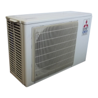
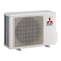
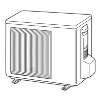
Identifies and labels main parts of the outdoor unit for different model series.
Detailed technical specifications for MSZ/MSY-A09/12NA models.
Detailed technical specifications for MSZ/MSY-A15/17NA models.
Detailed technical specifications for MSZ/MSY-A24NA models.
Details the test conditions used for SEER and HSPF ratings.
Provides dimensional drawings and required space for smaller outdoor units.
Provides dimensional drawings and required space for larger outdoor units.
Electrical wiring schematic for MUZ-A09/12/15/17NA outdoor units.
Electrical wiring schematic for MUY-A15/17NA outdoor units.
Electrical wiring schematic for MUZ-A24NA outdoor unit.
Electrical wiring schematic for MUY-A24NA outdoor unit.
Diagram showing refrigerant flow and components for specific MUZ/MUY models.
Diagram showing refrigerant flow and components for MUZ/MUY-A24NA models.
Details maximum piping lengths and height differences for all models.
Tables showing cooling capacity at various indoor/outdoor conditions.
Tables showing heating capacity at various indoor/outdoor conditions.
Graphical representation of capacity and input correction by inverter frequency.
Charts illustrating condensing and suction pressures under various conditions.
Describes the fan motor's operation interlocking with the compressor.
Explains the control sequence for the 4-way reversing valve based on operation mode.
Maps sensor inputs to actuator outputs for different unit models.
Details how to modify the defrost finish temperature via jumper wire.
Essential safety measures and preparation steps before troubleshooting.
Step-by-step guide to recall fault codes and interpret LED indicators.
Component checks, resistance tests, and diagnostic flowcharts for system issues.
Instructions on how to detach terminals with locking mechanisms.
Steps for removing the service panel, top panel, cabinet, and back panel.
Procedures for removing inverter, power, and control P.C. boards and related assemblies.
Steps for removing specific parts like R.V. coil, thermistors, fan motor, compressor, and 4-way valve.
Illustrated parts list for structural and functional components (non-RoHS and RoHS).
Illustrated parts list for electrical and electronic components (non-RoHS and RoHS).
Lists parts numbers for drain sockets and their assemblies.