BALANCER CHAIN <4B12>
ENGINE OVERHAUL
11B-51
9. After tightening them to the specified torque of 20
N
⋅m again, use special tool Angle gauge
(MB991614) to tighten them up to 135
°.
10.Pull out the hexagonal bar wrench from the
balancer module sprocket.
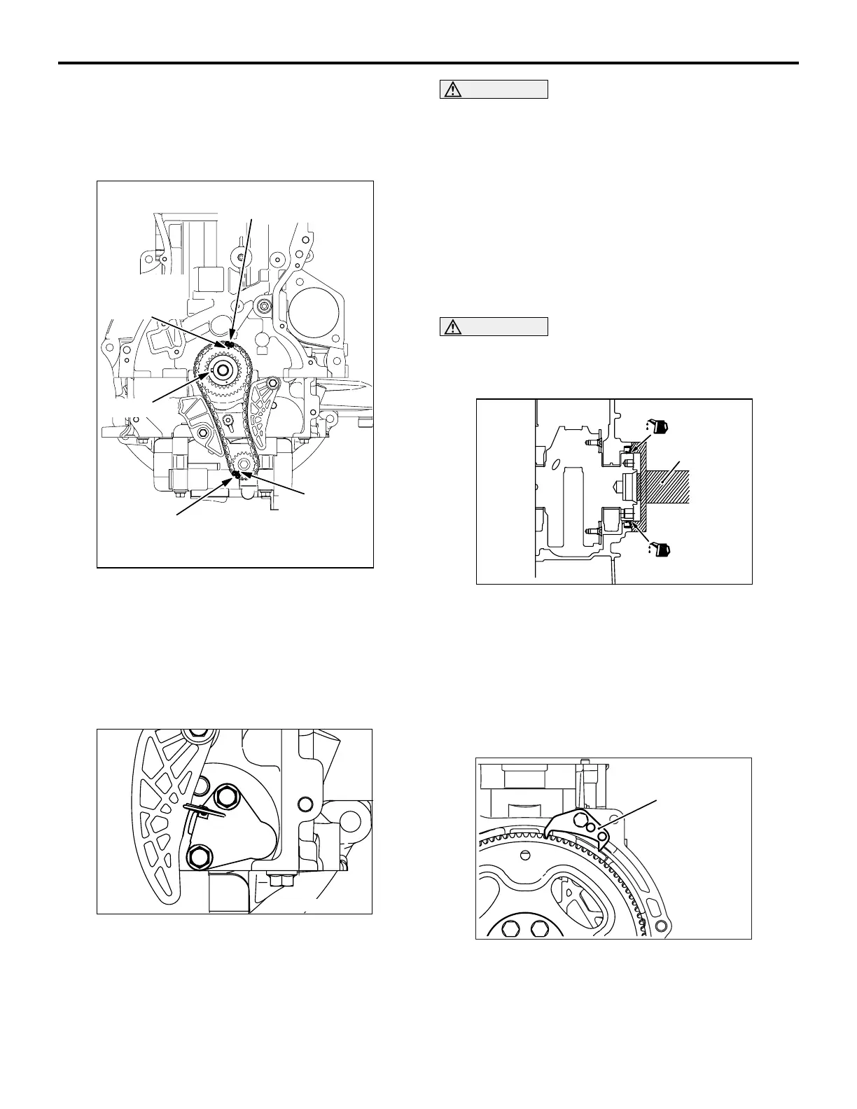
AK502923
Timing mark
link plate (orange)
Timing mark
link plate (blue)
Crank shaft
sprocket
timing mark
Key groove
Balancer shaf
sprocket
timing mark
AD
11.Make sure that the respective timing mark is
aligned with each other as illustrated.
12.Install the balancer chain tensioner lever and
balancer chain guide.
>>C<< BALANCER SHAFT CHAIN
TENSIONER INSTALLATION
AK502940
1. Attach the chain tensioner to the ladder frame.
CAUTION
Install the chain tensioner precisely in place after
installing the tensioner lever and chain guide to
prevent the plunger of the chain tensioner from
jumping out.
2. Remove the hard wire (piano wire, etc.) of φ1.5 or
hexagonal bar wrench (1.5 mm) from the
tensioner. This enables the plunger of the chain
tensioner to push the balancer shaft tensioner
lever to keep the balancer shaft chain tight.
>>D<< REAR OIL SEAL INSTALLATION
CAUTION
Do not apply oil to the circumference of the oil
seal and oil seal pressing hole on the cylinder
block side to prevent teeth from pulling out.
AK502871
AC
MD998718
After applying a small amount of engine oil to the oil
seal lip, use special tool Rear oil seal installer
(MD998718) to press fit the oil seal.
>>E<< DRIVE PLATE BOLT
INSTALLATION
1. Clean off sealant and oil of thread of crankshaft
and drive plate bolts.
AK503335
AC
MB991883
2. Use special tool Flywheel stopper (MB991883) to
secure the drive plate.

 Loading...