PISTON AND CONNECTING ROD
ENGINE OVERHAUL
11B-54
Enter cylinder No. for reassembly on the side of the
connecting rod big end.
<<B>> PISTON PIN REMOVAL
AK305415
AB
Push rod
Base
Guide B
Guide C
Guide D
(MB991659)
Guide A: 17.9 mm
Guide A: 18.9 mm
Guide A: 20.9 mm
Guide A: 21.9 mm
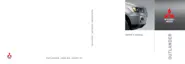
Special tool Piston pin setting tool (MD998780) con-
sists of parts shown in the illustration. Use also spe-
cial tool Guide D (MB991659) to remove the piston
pin.
AK603502
20
A
AC
Base
Guide D
Piston pin
Push rod
Front mark
Front mark
1. Insert the push rod into the piston pin from the
front mark side of the piston top surface, and
attach special tool Guide D (MB991659).
2. Set the piston and connecting rod assembly on
the base so that the front mark of the piston faces
upward.
3. Use a press to push the push rod and pull out the
piston pin.
NOTE: After pulling out the piston pin, organize
pistons, piston pins and connecting rods by cylin
-
der No.
INSTALLATION SERVICE POINTS
>>A<< PISTON PIN INSTALLATION
J2
J3
J4
J5
J1
AK503237
No.1
No.2
No.3
No.4
AC
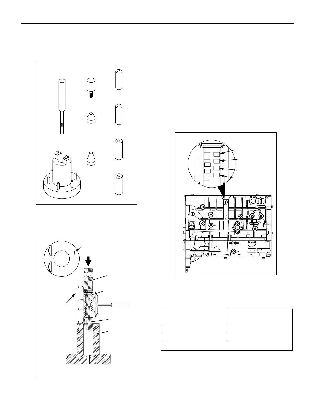
1. When replacing a piston, check the cylinder bore
size mark stamped on the illustrated position of
the cylinder block and select a corresponding
piston from the table below.
Cylinder bore size
mark
Piston size mark
A A
B B or None
C C

 Loading...