AK603503
20
A
AC
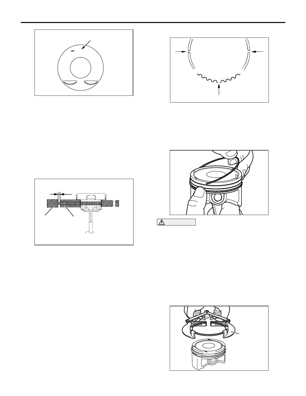
Piston mark size
PISTON AND CONNECTING ROD
ENGINE OVERHAUL
11B-55
NOTE: The piston size mark is indicated on the
piston top face.
2. Insert the push rod into the piston pin and attach
guide A.
3. Align the front mark of the piston with that of the
connecting rod to assemble.
4. Apply engine oil to the circumference of the piston
pin.
5. Insert the guide A side of the piston pin
assembled in section 1 into the pin hole from the
front mark side of the piston.
AK502517
AC
L
Guide A
Guide B
6. Screw guide B into guide A and open clearance
between guide A and guide B by 3 mm (make the
base in line with flushed surface) to assemble.
7. Set the piston on special tool piston setting base
so that its front mark faces upward.
8. Use a press to press fit the piston pin. If the press
fit load is below the standard value, replace the
piston pin (piston assembly) or connecting rod, or
both.
Standard value: 7,500 − 17,500 N
>>B<< OIL RING INSTALLATION
AK103812
AC
Upper
side
rail
closed
gap
Lower
side
rail
closed
gap
Spacer closed gap
1. Assemble the spacer of the oil ring into the piston
ring groove. Then, assemble the upper side rail,
and after this assemble the lower side rail.
NOTE: Install the side rail and end gap of the
spacer so that they are at the position as shown in
the illustration.
AK304891
CAUTION
The side rail may be broken if its end gap is wid-
ened by a ring expander as in other piston rings.
2. When assembling the side rail, push it by fingers,
after fitting one end of the side rail into the piston
groove, for easy assembly.
3. After assembling the oil ring into the piston, make
sure that the side rail turns smoothly to either
direction.
>>C<< PISTON RING NO. 2 / PISTON
RING NO. 1 INSTALLATION
AK304892
AB
Piston ring
expander

 Loading...