8-12 Chapter 8 Clutch and driveline
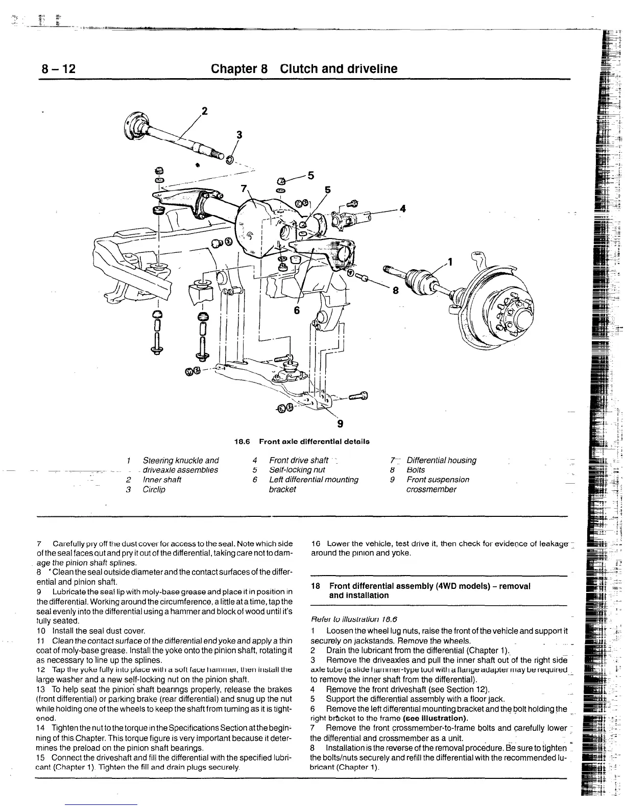
18.6 Front axle differential details
1 Steering knuckle and 4 Front drive shaft -.
driveaxle assemblies 5 Self-locking nut
2 Inner shaft 6 Left differential mounting
3 Circlip bracket
7:-
8
9
Differential housing
Bolts
Front suspension
crossmember
7 Carefully pry off the dust cover for access to the seal. Note which side
of thesealfacesoutandpryitoutof thedifferential, takingcarenottodam-
age the pinion shaft splines.
8 ‘Clean the seal outside diameter and the contact surfaces of the differ-
ential and pinion shaft.
9 Lubricate the seal lip with moly-base grease and place It in position In
the differential. Working around the circumference, a little at a time, tap the
seat evenly into the differential using a hammer and block of wood until it’s
fully seated.
10 Install the seal dust cover.
11 Clean the contact surface of the differential end yoke and apply a thin
coat of moly-base grease. Install the yoke onto the pinion shaft, rotating it
as necessary to line up the splines.
12 Tap the yoke fully into place with a soft face hammer, then install the
large washer and a new se!f-locking nut on the pinion shaft.
13 To help seat the pinion shaft bearings properly, release the brakes
(front differential) or parking brake (rear differential) and snug up the nut
while holding one of the wheels to keep the shaft from turning as it is tight-
ened.
14 Tighten the nut to the torque in the Specifications Section atthe begin-
ning of this Chapter. This torque figure is very important because it deter-
mines the preload on the pinion shaft bearings.
15 Connect the driveshaft and fill the differential wtth the specified lubri-
cant (Chapter 1). Tighten the fill and drain plugs securely.
16 Lower the vehicle, test drive it, then check for evidence of leakage 1
around the prnion and yoke,
18 Front differential assembly (4WD models) - removal
and installation
Refer to illustration 18.6
1 Loosen the wheel lug nuts, raise the front of the vehicle and support it
securely on jackstands. Remove the wheels.
2 Drain the lubricant from the differential (Chapter 1) m -
3 Remove the driveaxles and pull the inner shaft out of the right side
axle tube (a slide hammer-type tool with a flange adapter may be required
.-
to remove the inner shaft from the differential).
4 Remove the front driveshaft (see Section 12).
5 Support the differential assembly with a floor tack.
6 Remove the left differential mounting bracket and the bolt holding the
right b&cket to the frame (see illustration).
7 Remove the front crossmember-to-frame bolts and carefully lower
the differential and crossmember as a unit.
8 Installation is the reverse of the removal procedure. E&sure to tighten 1
the bolts/nuts securely and refill the differential with the recommended lu-
bricant (Chapter 1).
f
 Loading...


