Chapter 8 Clutch and driveline ’
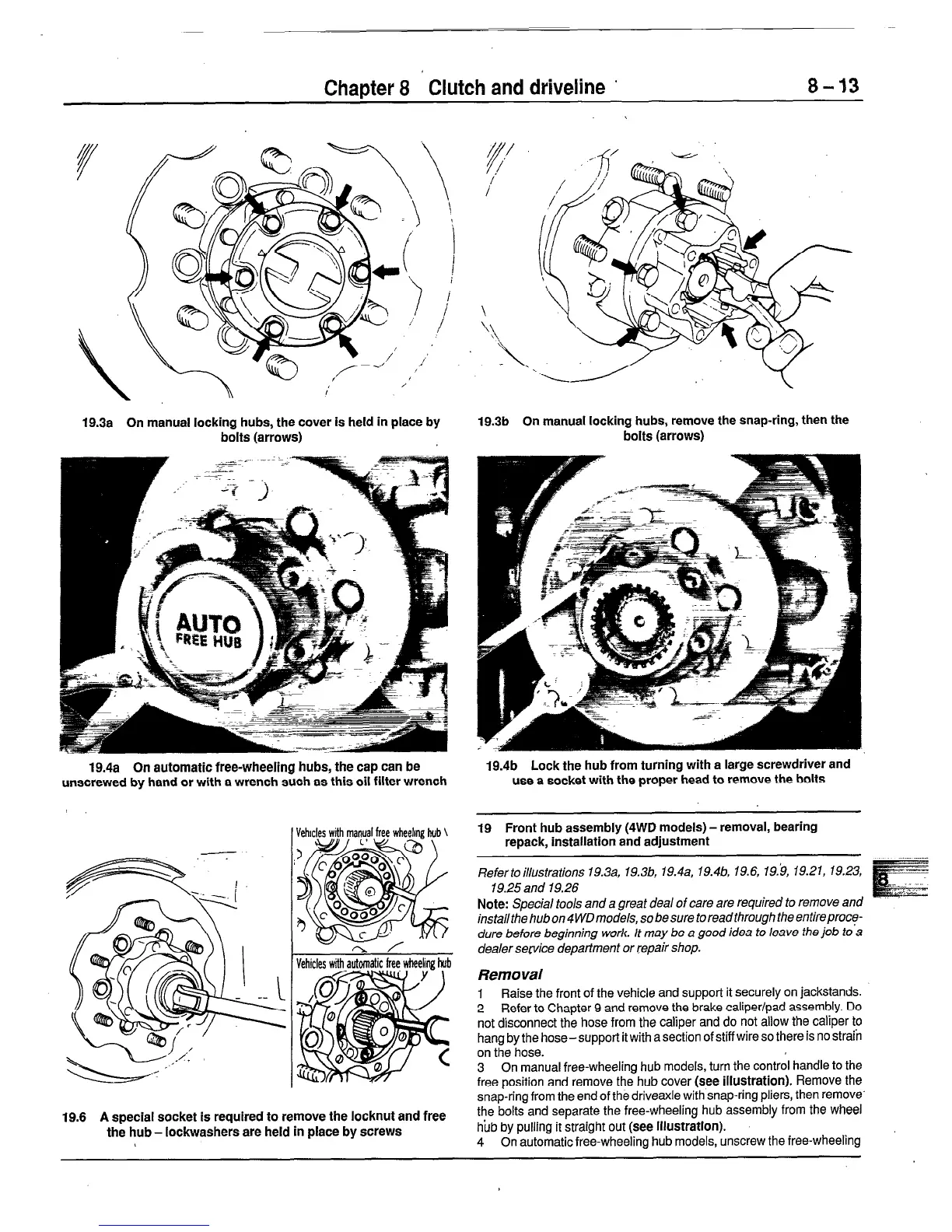
19.3a On manual locking hubs, the cover is held in place by
bolts (arrows)
19.3b On manual locking hubs, remove the snap-ring, then the
bolts (arrows)
19.4a On automatic free-wheeling hubs, the cap can be
unscrewed by hand or with a wrench such as this oil filter wrench
19.4b Lock the hub from turning with a large screwdriver and
use a socket with the proper head to remove the bolts
19.6 A special socket is required to remove the locknut and free
the hub - lockwashers are held in place by screws
19 Front hub assembly (4WD models) - removal, bearing
repack, installation and adjustment
Refertoillustrations 19.3a, 19.3b, 19.4a, 19.4b, 19.6, 19.‘9, 19.21, 19.23,
19.25 and 19.26
Note:
Special too/s and a great deal of care are required to remove and
install the hub on 4 WD models, so be sure to read through the entireproce-
dure before beginning work. It may be a good idea to leave the job to a
dealer sewice department or repair shop.
Removal
1 Raise the front of the vehicle and support it securely on jackstands.
2 Refer to Chapter 9 and remove the brake caliper/pad assembly. Do
not disconnect the hose from the caliper and do not allow the caliper to
hang by the hose-support it with a section of stiff wire so there is no strafn
on the hose.
3 On manual free-wheeling hub models, turn the control handle to the
free position and remove the hub cover (see illustration). Remove the
snap-ring from the end of the driveaxle with snap-ring pliers, then remove
the bolts and separate the free-wheeling hub assembly from the wheel
hub by pulling it straight out (see illustration).
4 On automatic free-wheeling hub models, unscrew the free-wheeling
 Loading...


