EasyManua.ls Logo

Mitsubishi PK12FK - Refrigerant System Diagram

Mitsubishi PK12FK
70 pages
To Next Page IconTo Next Page
To Previous Page IconTo Previous Page
Loading...
OC196A-23
Unit : inch
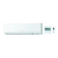
Remote controller (PK12/18/24/30/36FK1, PK18/24/30/36FK2)
FILTER
CHECK MODE
TEST RUN
TIMER OFF TIMER
CHECK SET TEMP.
CLOCK AUTO AUTO
START STOP
SWING
FAN
SPEED
5-1/8
4-3/4
3/4
3/32
23/32
AUTO
RETURN
Pipe temperature
thermistor
RT2
Distributor
Refrigerant pipe
(option)
{3/8"
(with heat insulator)
Refrigerant pipe
(option)
{5/8"
(with heat insulator)
Strainer
Flared connection
Flared connection
Pipe temperature
thermistor
RT2
Distributor
Refrigerant pipe
(option)
{1/2"
(with heat insulator)
Refrigerant pipe
(option)
{3/4"
(with heat insulator)
Strainer
Flared connection
Flared connection
PK12/18/24FK
PK12/18/24FK1
PK18/24FK2
PK30/36FK
PK30/36FK1
PK30/36FK2
7
REFRIGERANT SYSTEM DIAGRAM
COOLING
Refrigerant flow
OC196A--1.qxp 1.12.19 10:35 AM Page 23

Related product manuals