3 - 18 3 - 18
3 SPECIFICATIONS
MELSEC-Q
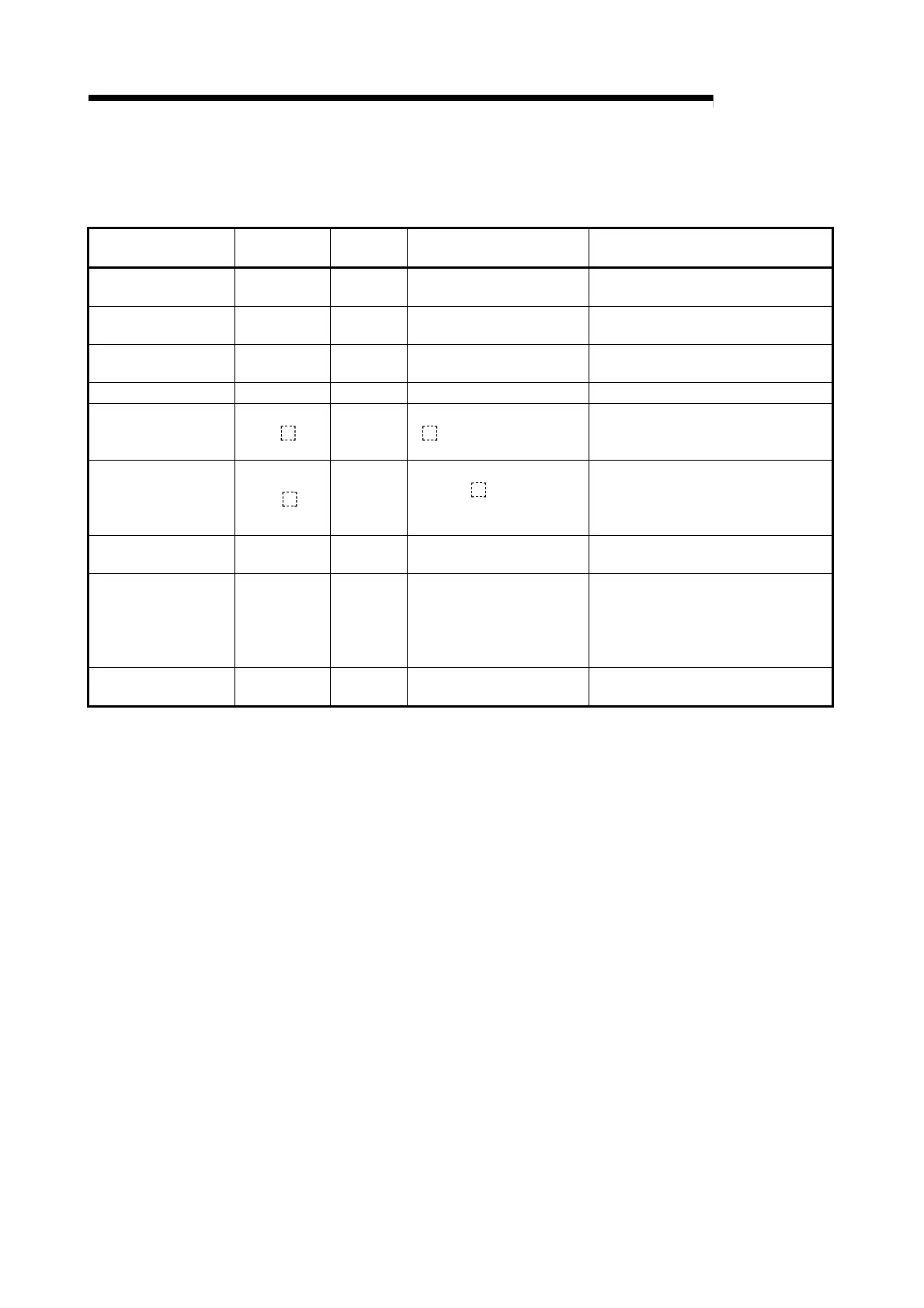
(2) Number of steps required for expressing the SFC diagram as SFC dedicated instructions
The following table shows the number of steps required for expressing the SFC diagram as
SFC dedicated instructions.
Name
Ladder
Expression
Number of
Steps
Description Required Number of Steps
SFCP START
instruction
[SFCP] 1
Indicates the SFC program
START
1 per program
SFCP END instruction [SFCPEND] 1
Indicates the SFC program
END
1 per program
Block START
instruction
[BLOCK BLm] 1 Indicates the block START 1 per block
Block END instruction [BEND] 1 Indicates the block END 1 per block
Step START
instruction
[STEP
Si] 2
Indicates the step START
(“
” varies according to the
step attribute)
1 per step
Transition START
instruction
[TRAN
TRj] 2
Indicates the transition
START (“
” varies
according to the step
attribute)
1 per transition condition
Coupling check
instruction
[TAND Si] 2
“Coupling completed” check
occurs at parallel coupling
“[Number of parallel couplings] - [1]”
per parallel coupling
Transition designation
instruction
[TSET Si] 2
Designates the transition
destination step
For serial transitions and selection
transitions, 1 per transition condition;
for parallel branching transitions, the
number of steps is the same as the
number of parallel couplings
Step END instruction [SEND] 1
Indicates the step / transition
END
1 per step

 Loading...


