4 - 1 4 - 1
4 SFC PROGRAM CONFIGURATION
MELSEC-Q
4. SFC PROGRAM CONFIGURATION
This chapter explains the SFC program symbols, SFC control instructions and SFC information
devices that comprise an SFC program.
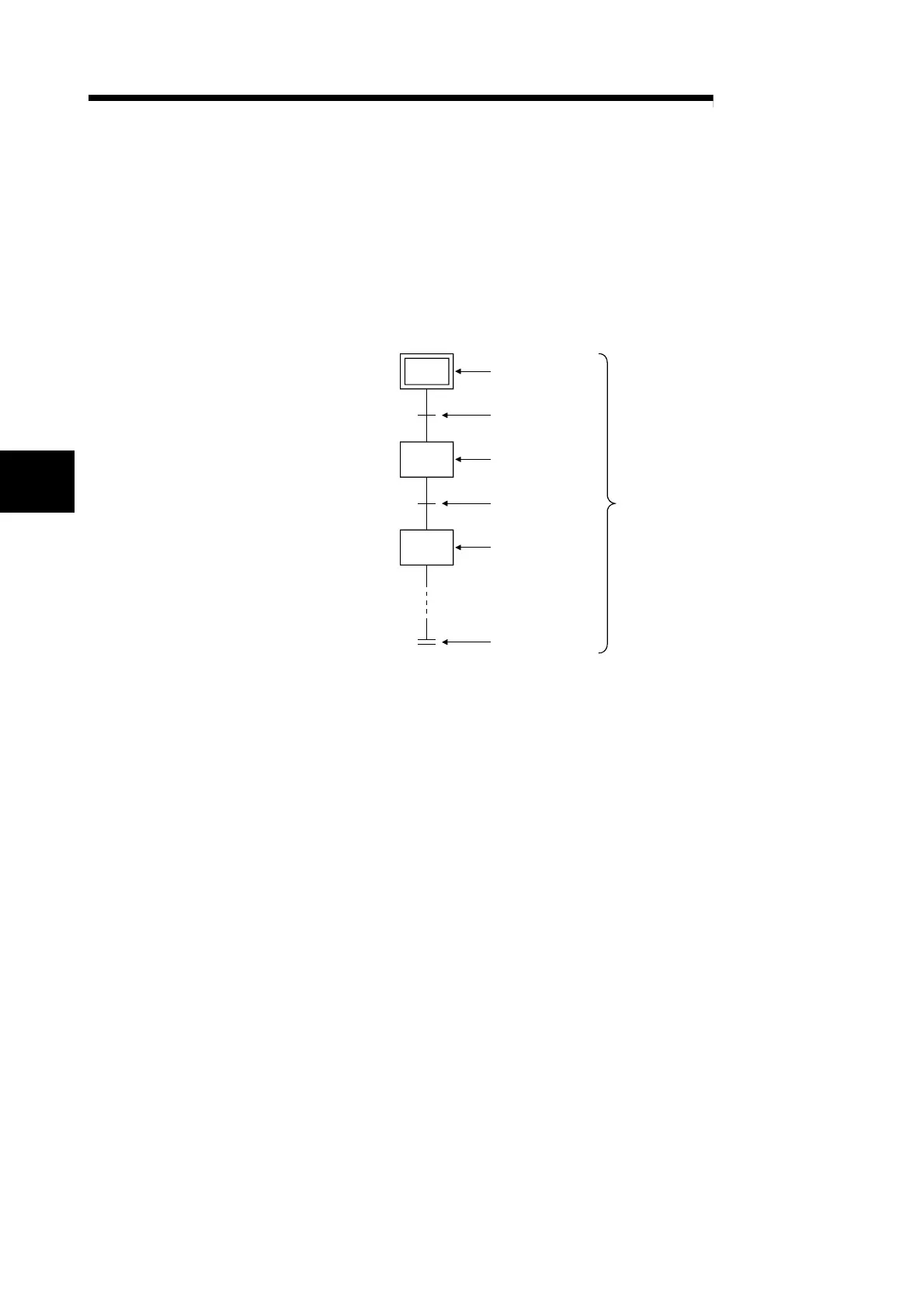
(1) As shown below, an SFC program consists of an initial step, transition conditions, intermediate
steps, and an END step. The data beginning from the initial step and ending at the END step is
referred to as a block.
Initial step
Transition condition
Transition condition 0(t0)
Step
Transition condition
Transition condition 1(t1)
Step 1(S1)
Step
End step
Step 2(S2)
Block
Step 0(S0)
(2) An SFC program starts at an initial step, executes a step following a transition condition in due
order every time that transition condition is satisfied, and ends a series of operations at an end
step.
(a) When the SFC program is started, the initial step is executed first.
While the initial step is being executed, whether the transition condition following the initial
step (transition condition 0 (t0) in the figure) has been satisfied or not is checked.
(b) Only the initial step is executed until transition condition 0 (t0) is satisfied.
When transition condition 0 (t0) is satisfied, the execution of the initial step is stopped, and
the step following the initial step (step 1 (S1) in the figure) is executed.
While step 1 (S1) is being executed, whether the transition condition following step 1
(transition condition 1 (t1) in the figure) has been satisfied or not is checked.
(c) When transition condition 1 (t1) is satisfied, the execution of step 1 (S1) is stopped, and the
next step (step 2 (S2) in the figure) is executed.
(d) Every time the transition condition is satisfied in order, the next step is executed, and the
block ends when the end step is executed.
4

 Loading...


