3 - 3
MELSEC-Q
3 SPECIFICATIONS
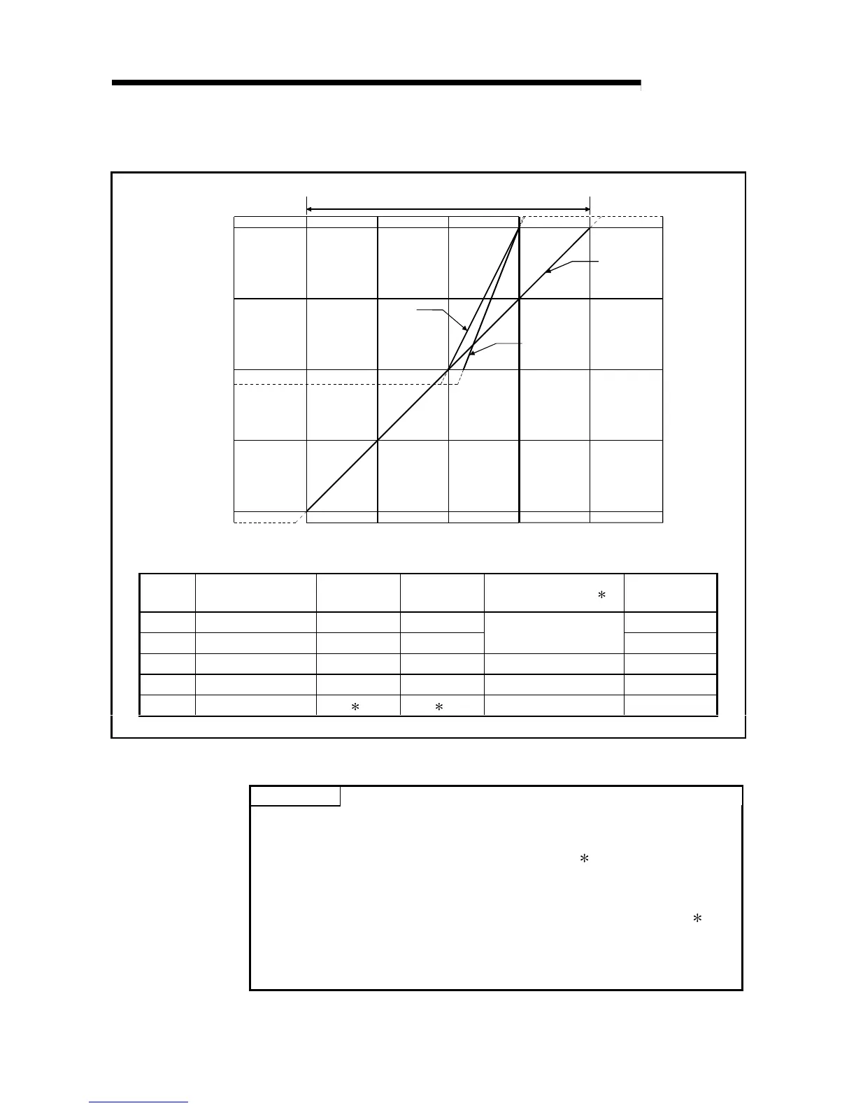
(1) Voltage input characteristic
A voltage input characteristic graph is shown in Figure 3.1.
Digital output value
Analog input voltage (V)
1)
2)
1
4095
4000
2000
0
–2000
–4000
–96
–4096
–15 –10
–5
0 5 10 15
Analog input practical range
3) 4)
Number
Analog input
range setting
Offset value Gain value Digital output value 2
Maximum
resolution
1) 1 to 5 V 1 V 5 V 1.0 mV
2) 0 to 5 V 0 V 5 V
0 to 4000
1.25 mV
3) –10 to 10 V 0 V 10 V –4000 to 4000 2.5 mV
4) 0 to 10 V 0 V 10 V 0 to 4000 2.5 mV
— User range setting 1 1 –4000 to 4000 —
Figure 3.1 Voltage input characteristic
POINT
(1) Do not input an analog input voltage of more than ± 15 V. The input elements
may be damaged.
(2) Set the offset/gain values for the user setting range
1 within a range in which
the following conditions are satisfied.
{ (Gain value) – (Offset value) } > 1.5 V
(3) When an analog value that exceeds the range for the digital output value
2 is
entered, the digital output value will be fixed at the maximum or minimum value.
• For 0 to 4000, the range for the digital output value is from –96 to 4095.
• For –4000 to 4000, the range for the digital output value is from –4096 to 4095.
 Loading...

