4 - 8
MELSEC-Q
4 SETUP AND PROCEDURES BEFORE OPERATION
4.5 Switch Setting for Intelligent Function Module
The settings for the intelligent function module are performed using the I/O assignment
settings for GPPW.
(1) The intelligent function module switches consist of switches 1 to 5 and are set
using 16 bit data. When the intelligent function module switches are not set, the
default value for switches 1 to 5 is 0.
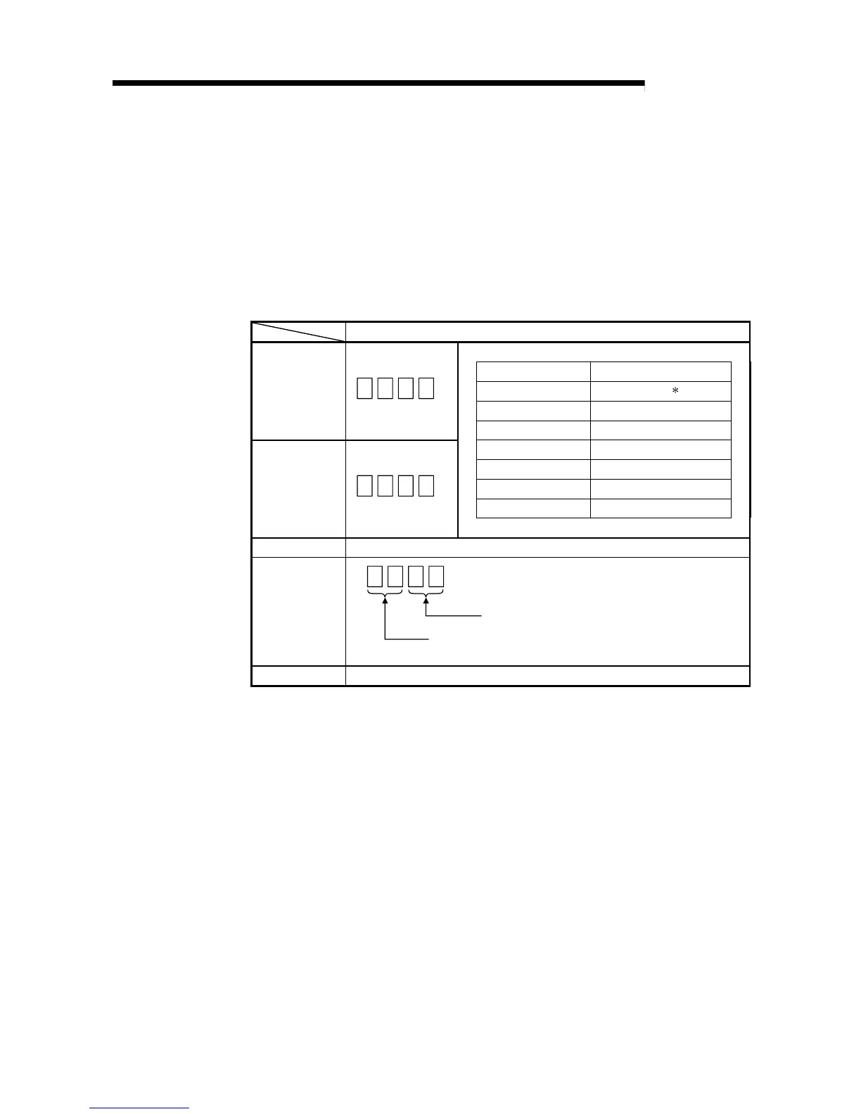
Table 4.1 Switch setting item
Setting item
Analog input range Input range setting value
4 to 20 mA 0
H
1
0 to 20 mA 1
H
Switch 1
Input range setting
H
CH4CH3CH2CH1
1 to 5 V 2
H
0 to 5 V 3
H
– 10 to 10 V 4
H
0 to 10 V 5
H
User range setting F
H
Switch 2
Input range setting
H
CH8CH7CH6CH5
Switch 3 Not used
Switch 4
H
00
H
: With temperature drift correction
Other than 00
H
: Without temperature drift correction
00
H
: Normal mode (A/D conversion processing)
Other than 00
H
: Offset/gain setting mode
Switch 5 0 : Fixed
Depending on the type of module used, the settings for A/D unit input range are shown
below.
• Q64AD.................. 0
H
to 5
H
, F
H
• Q68ADV............... 0
H,
2
H
to 5
H
, F
H
*1 When the setting is 0
H
, the input operating range will be 0t o 10V.
• Q68ADI................. 0
H,
1
H
, F
H
 Loading...

