3 - 8
MELSEC-Q
3 SPECIFICATIONS
3.2.2 Maximum and minimum values hold function
(1) The maximum and minimum digital output values for each channel are stored in buffer
memory addresses 30 to 45 (Un\G30 to Un\G45).
(2) When the operating condition setting completed flag (X09) turns OFF, the values
are cleared to 0 and new maximum and minimum values are stored when
conversion begins.
(3) Since the area for storing the maximum and minimum values can be rewritten with
the sequence program, the maximum and minimum values within a specific period
of time can be checked.
3.3 I/O Signals for the PLC CPU
3.3.1 List of I/O signals
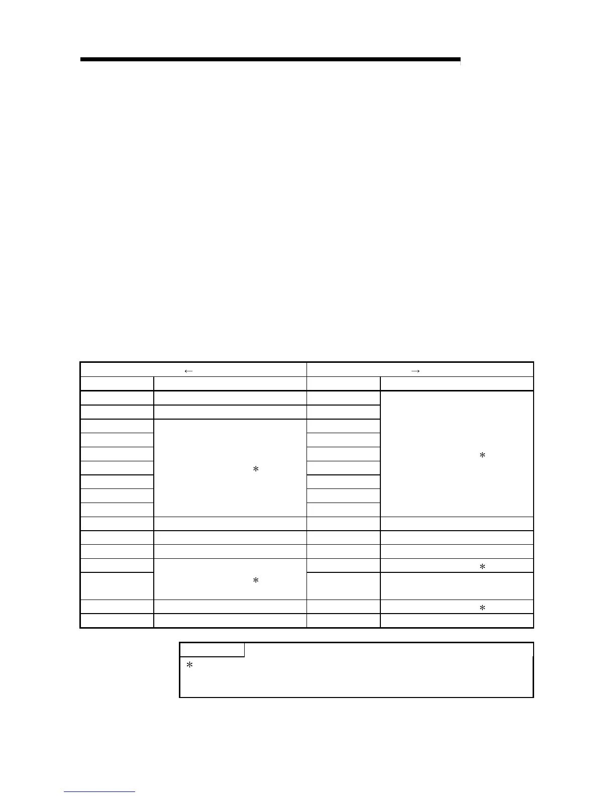
Table 3.3 shows a list of the I/O signals for the A/D conversion modules.
Table 3.3 List of I/O signal
Signal direction CPU A/D conversion module Signal direction CPU A/D conversion module
Device No. (Input) Signal name Device No. (Output) Signal name
X00 Module READY Y00
X01 Temperature drift compensation flag Y01
X02 Y02
X03 Y03
X04 Y04
X05 Y05
X06 Y06
X07 Y07
X08
Use prohibited 1
Y08
Use prohibited
1
X09 Operating condition setting completed flag Y09 Operating condition setting request
X0A Offset/gain setting mode flag Y0A User range write request
X0B Channel change completed flag Y0B Channel change request
X0C Y0C Use prohibited 1
X0D
Use prohibited
1
Y0D
Maximum value/minimum value reset
request
X0E A/D conversion completed flag Y0E Use prohibited 1
X0F Error flag Y0F Error clear request
POINT
1 These signals cannot be used by the user since they are for system use only.
If these are turned ON/OFF by the sequence program, the functioning of the
A/D conversion module cannot be guaranteed.
 Loading...

