5 - 64
MELSEC-Q
5 DATA USED FOR POSITIONING CONTROL
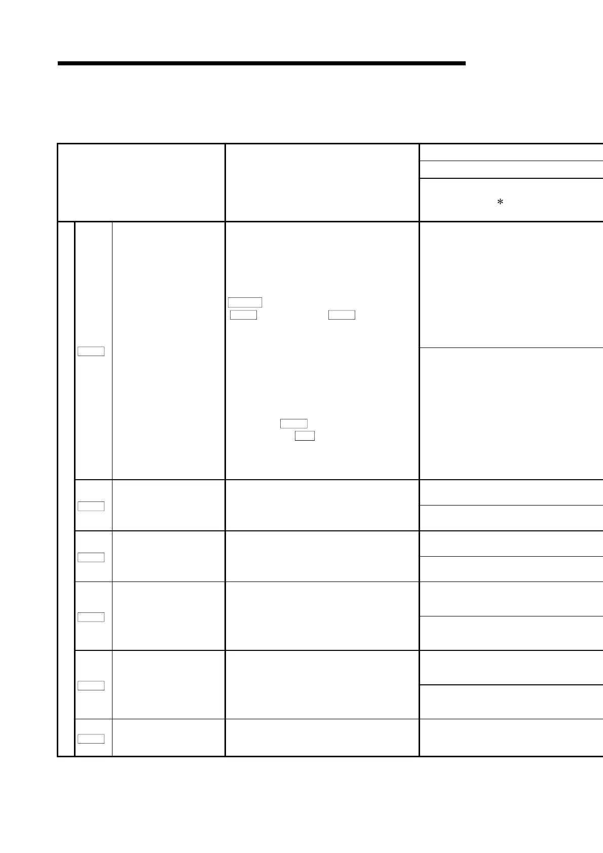
5.2.8 Servo adjustment parameters
Item Setting details
Setting value
1
0 to 100.0[times]
Pr.112
Load inertia ratio
Used to set the ratio of the load inertia to the inertia
moment of the servomotor.
When auto tuning is selected, the result of auto tuning
is automatically used.
POINT
Pr.112
Load inertia ratio to
Pr.117
Speed integral
compensation
is transferred to servo amplifier in PLC
CPU power on, reset and PLC READY signal (Y0)
on. When auto tuning is executed, it is changed to the
optimum value inside servo amplifier.
The result of auto tuning is transferred to QD75 at this
time.
When auto tuning is invalid and wants to keep gain
adjustment result by servo amplifier, a reading stock
is executed by
Cd.102
Servo amplifier read to QD75.
After that, execute
Cd.1
Flash ROM write request,
and keep it in the flash ROM.
0 to 300.0[times]
4 to 1000[rad/s]
Pr.113
Position loop gain 1
Used to set the gain of position loop 1. Increase the
gain to improve trackability performance in response
to the position command.
4 to 2000[rad/s]
20 to 5000[rad/s]
Pr.114
Speed loop gain 1
Normally this parameter setting need not be
changed. Higher setting increases the response
level but is liable to generate vibration and/or noise.
20 to 8000[rad/s]
1 to 500[rad/s]
Pr.115
Position loop gain 2
Used to set the gain of the position loop.
Set this parameter to increase position response to
load disturbance.
Higher setting increases the response level but is
liable to generate vibration and/or noise.
1 to 1000[rad/s]
20 to 8000[rad/s]
Pr.116
Speed loop gain 2
Set this parameter when vibration occurs on
machines of lowrigidity or large backlash.
Higher setting increases the response level but is
liable to generate vibration and/or noise.
20 to 20000[rad/s]
Servo adjustment parameters
Pr.117
Speed integral compensation Used to set the constant of integral compensation. 1 to 1000[ms]

 Loading...