5 - 68
MELSEC-Q
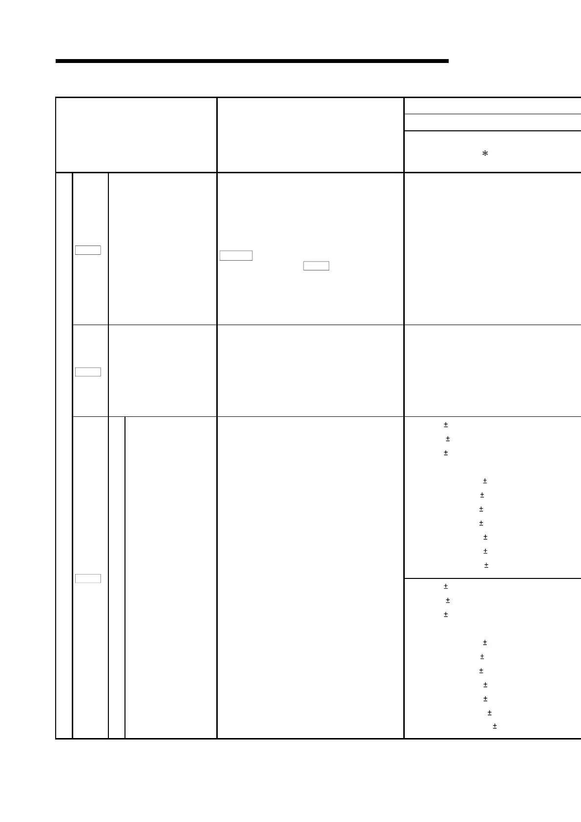
5 DATA USED FOR POSITIONING CONTROL
Item Setting details
Setting value
1
Pr.120
In-position range
Used to set the droop pulse range in which the in-
position signal will be output to the servo system
controller.
POINT
Only MR-J2S-B sets up
Pr.106
F
eed back pulse in
the feed back pulse unit.
0 to 50000[PLS]
Pr.121
Electromagnetic brake
sequence output
Used to set a time delay from when the
electromagnetic brake interlock signal (MBR) turns
off until the base circuit is shut off.
0 to 1000[ms]
0: Speed ( output)
1: Torque ( output)
2: Speed ( output)
3: Torque ( + output)
4: Current command ( output)
5: Command speed ( output)
6: Droop pulses 1/1 ( output)
7: Droop pulses 1/4 ( output)
8: Droop pulses 1/16 ( output)
9: Droop pulses 1/32 ( output)
A: Droop pulses 1/64 ( output)
0: Speed ( output)
1: Torque ( output)
2: Speed ( output)
3: Torque (+ output)
4: Current command ( output)
5: Command speed ( output)
6: Droop pulses 1/1 ( output)
7: Droop pulses 1/16 ( output)
8: Droop pulses 1/64 ( output)
9: Droop pulses 1/256 ( output)
A: Droop pulses 1/1024 ( output)
Servo adjustment parameters
Pr.122
Analog monitor output
Monitor output mode
selection
(ch1, ch2)
Used to set the output signal from analog monitor ch1
and ch2 of the servo amplifier.

 Loading...