Appendix - 69
MELSEC-Q
APPENDICES
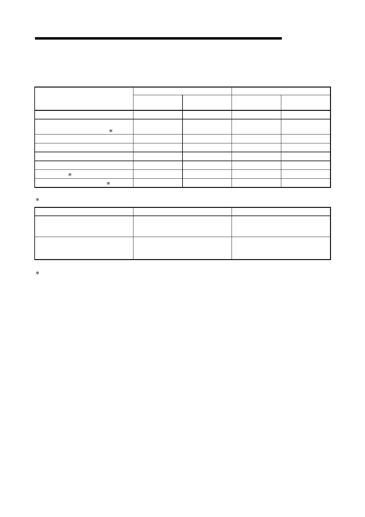
(5) Input/output signal comparisons
Input signal comparisons
A1SD75 QD75
Name
Logic (initial status)
Logic switch with
parameters
Logic (initial status)
Logic switch with
parameters
In-position signal Negative logic Not possible – –
Manual pulse generator A phase
Manual pulse generator B phase
1
Negative logic
(multiple of 4)
Not possible
Negative logic
(multiple of 4)
Possible
Near-point signal Negative logic Not possible Negative logic Possible
Stop signal Negative logic Not possible Negative logic Possible
Upper limit Negative logic Not possible Negative logic Possible
Lower limit Negative logic Not possible Negative logic Possible
External start 2 Negative logic Not possible Negative logic Possible
Speed-position switching signal 2 Negative logic Not possible Negative logic Possible
1: Comparisons about manual pulse generator A phase/B phase.
A1SD75 QD75
No. of connectable manual pulse
generators
1 generator/1 axis 1 generator/1 module
Mode selection (with parameter) Not possible
Possible
Multiple of 1 mode, multiple of 2 mode,
multiple of 4 mode, PLS/SIGN mode
2: With the QD75, the "external start signal" and "speed-position switching signal" are combined into the "external command
signal/switching signal".

 Loading...