Appendix - 89
MELSEC-Q
APPENDICES
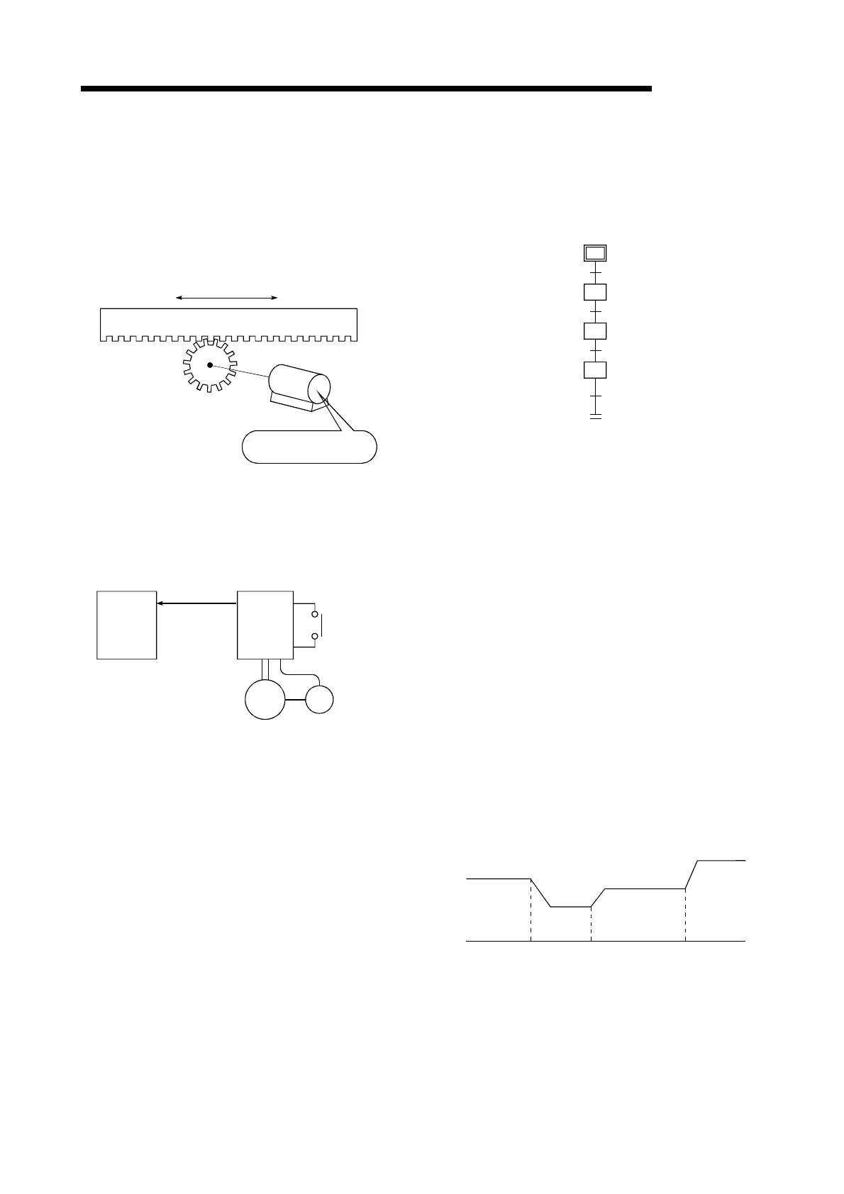
SERVO LOCK
In positioning using a servomotor, stepping
motor, etc., working power is required to hold
the machine at the stop position.
(The position will be lost if the machine is
moved by external power.)
This kind of state is called servo lock or servo
lock torque.
M
Table
Motor holds the position
at the stop position.
SERVO ON
The servo module will not operate if the drive
unit is in a normal state and this servo ON
signal is OFF.
QD75
PLG
READY
Drive
unit
Servo ON
Motor Encoder
SERVOMOTOR
A motor that rotates true to the command.
Servomotors are highly responsive, and can
carry out frequent high-speed and high-
accuracy starts and stops.
DC and AC types are available, as well as
large-capacity motors. A pulse generator
accessory for speed detection is common, and
feedback control is often carried out.
SETTING UNIT
This is one setting item of the positioning
reference parameters. The unit to be used is
designated as mm, inch, degree, or pulse.
SFC (Sequential Function Chart)
A sequential function chart is a programming
method optimally structured for running a
machine's automatic control in sequence with
the PLC.
Start preparation
Start preparations OK
Execution of advance
operation servo program
Positioning complete
Execution of extrusion
operation servo program
Execution of retract
operation servo program
Positioning complete
Positioning complete
SKIP FUNCTION
When a SKIP signal is input, the positioning
being executed is interrupted, the motor is
deceleration stopped, and the next positioning
is automatically carried out.
SLAVE AXIS
During interpolation operation, the positioning
data is partially ignored on this side. This axis
is moved by the master axis data.
SPEED CHANGING
The positioning speed can be changed
between low and high speed.
1) Up to 9 continuous points can be
designated in the pattern, and the feed
direction is in the same direction.
2) The speed can also be changed by an
external signal, with no limit to the No. of
changes.
LS1 LS2 LS3
Speed change by limit switches (external signals)

 Loading...