3 - 11 3 - 11
MELSEC-Q
3 SPECIFICATIONS
3.2.3 Slave function (I/O communication function)
The I/O communication function executes the communication of the I/O data with the
master node using the polling method.
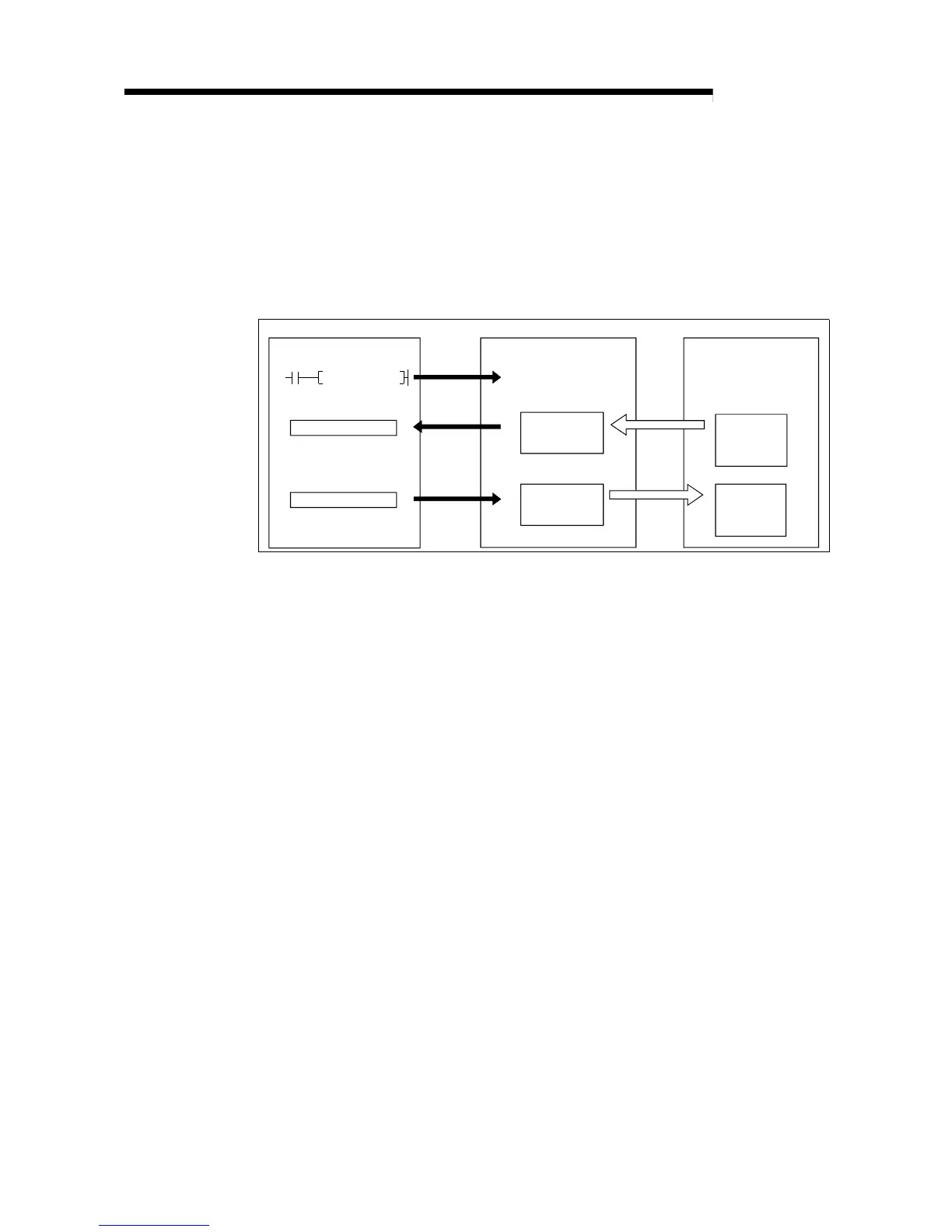
(1) When GX Configurator-DN is used
The following explains the I/O communication function when the GX
Configurator-DN is used.
PLC CPU QJ71DN91 Master node
I/O communication
request
1)
Slave function
receive
data area
0B00
H
0B3F
H
4)
0C00
H
0C3F
H
SET Y11
3)
Slave function
transmit
data area
Transmission
Reception
5)
2)
X
Y
[I/O communication]
1) Communication with the master node starts when the I/O
communication request (Y11) is turned ON.
[Reception data]
2) Transmission data from the master node is automatically stored in the
"slave function receive data" area of the buffer memory in the
QJ71DN91.
3) Transmission data from the mater node, which is stored in the "slave
function receive data" area of the buffer memory, is loaded onto the
PLC CPU by the auto refresh setting.
[Transmission data]
4) With the auto refresh setting, the ON/OFF information to be sent to the
master node is written in the "slave function transmit data" area of the
buffer memory.
5) The ON/OFF information, which is stored in the "slave function transmit
data" area of the buffer memory, is automatically sent to the master
node.
 Loading...


