ELECTRICAL SYSTEM
12-13
2.5 Inspecting and adjusting after reassembling
2.5.1 Inspecting pinion clearance
&$87,21
Do not apply current continuously for longer than 10
seconds.
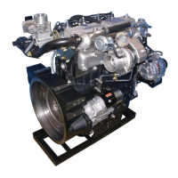
(1) Since connecting the wires of the reassembled starter as
shown in the diagram causes the pinion to extends and
rotate slowly, disconnect the connector from terminal
M to stop the rotation.
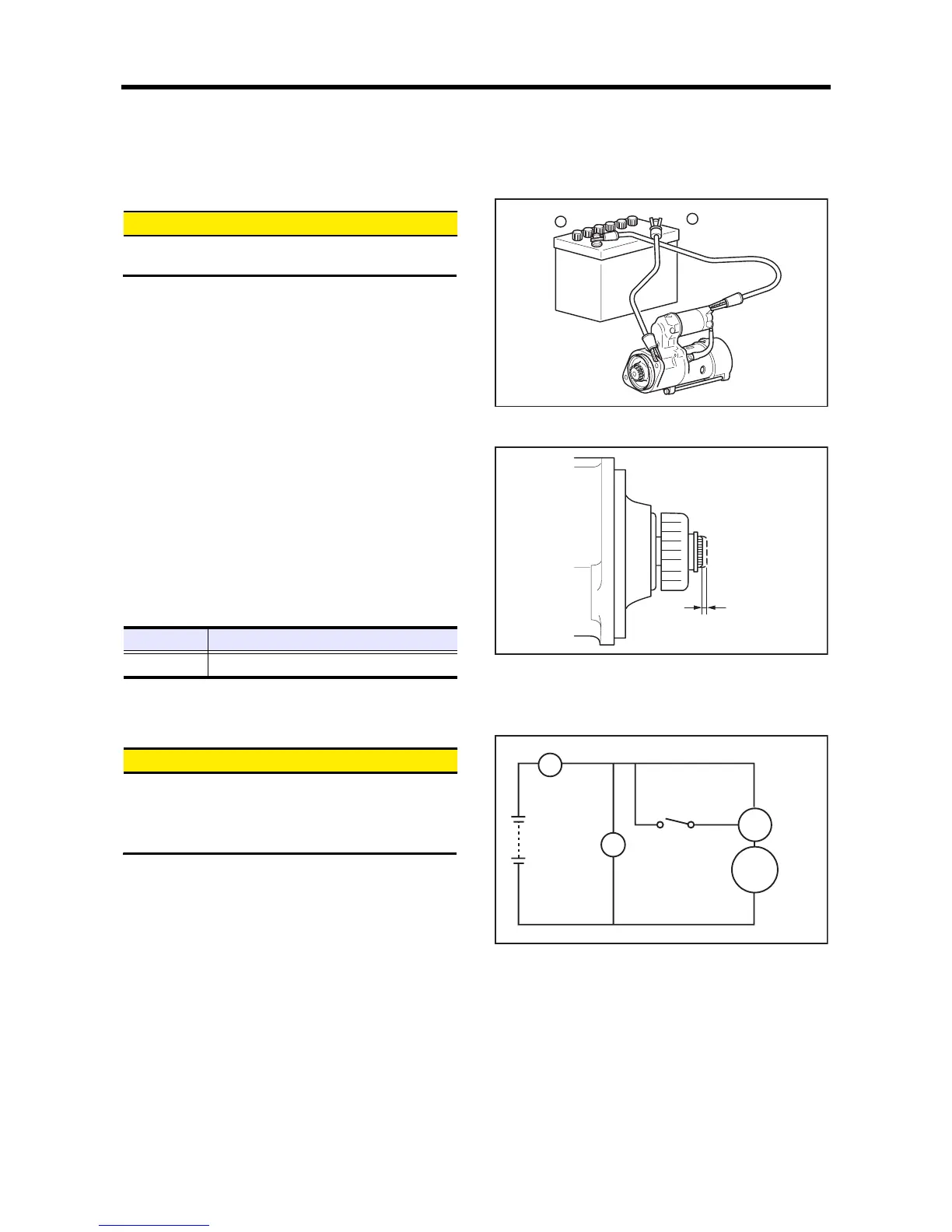
(2) Lightly push the tip of the extended pinion shaft with a
finger, and measure the distance of the shaft movement
to obtain the pinion gap measurement.
Adjust the pinion gap by varying the number of
packings installed at the magnetic switch section so that
it conforms to the standard value. When the number of
packings is increased, the pinion gap decreases.
If proper adjustment cannot be achieved by varying the
number of packings, replace the lever.
Ajusting pinion gap(1)
Ajusting pinion gap(2)
2.5.2 No load test
&$87,21
Use as thick a wire as possible and firmly tighten each
terminal.
When detecting the rotation at the tip of the pinion, be
careful, as the pinion pops out during operation.
(1) Connect the starter to the circuit as shown in the
illustration.
(2) In normal condition, the pinion pops out when the
switch is turned ON, and the starter rotates at or more
the specified rotation speed.
If the terminal voltage, current or rotation speed does
not meet the standard, disassemble, inspect and repair
the starter.
Test at no load
Item Standard
Pinion gap 0.5 to 2.0 mm [0.020 to 0.079 in.]
Terminal S
Terminal M
Battery
Pinion gap
A
V
B
M
S
Ammeter
Battery
Volt meter
Switch
Switch
Starter
 Loading...