Printed in Japan
Mitutoyo Corporation 1-20-1 Sakado, Takatsu-ku, Kawasaki City, Kanagawa 213-8533
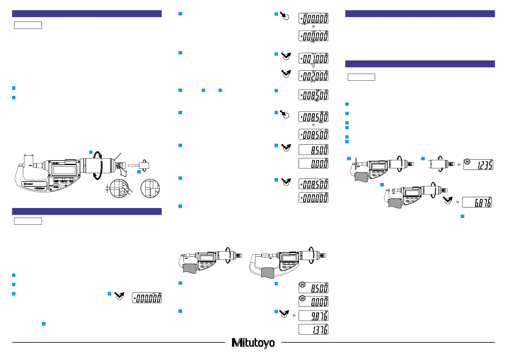
4. Measuring Force Setting
• When setting the measuring force, be sure to retract the spindle to position (A), where the
thimble stops rotating. If the spindle is not sufciently retracted, the proper measuring force
cannot be set.
• Slowly turn the thimble. If the spindle forcibly reaches position (A), where rotation stops, it may
lead to damage.
• After changing the measuring force, be sure to perform reference point setting. Otherwise, this
may cause errors. (Refer to "5. PRESET Value (Reference Point) Setting")
• Set the measuring force within the specications. Measuring force lower than the specication
range is not guaranteed, and spindle action will be negatively affected.
This product is a variable measuring force type micrometer. Measuring force settings can be
changed as follows.
1
Slowly retract the spindle to the position (A) where the thimble cannot be turned any further.
A
≧
maximum measurement length + 0.5 mm
2
Turn the measuring force selector with the provided slotted screwdriver to set the measuring
force.
Tips
Measuring force values (a) and scale lines (b) are indicated on the measuring force selector.
Adjust so that the scale line for the target measuring force is on the edge of the cover for
measuring force selector, and the central line (c) is within the setting range [between the two
lines (c)] of the cover for the measuring force selector.
Figure B below: Setting example for measuring force 0.5 N
Figure C below: Setting example for measuring force 2 N
Rotate the measuring force selector twice, to move it by one measuring force setting graduation.
A
B
c
b
a
C
1
2
2
4
Cover for measuring force
selector
5. PRESET Value (Reference Point) Setting
• For reference point setting, use a periodically inspected reference gage (gauge block,
micrometer standard bar, etc.).
• Reference point setting and measurement should be made in the same orientation and
conditions and with the same procedure as below.
• When using CLM-DKX, if measuring with only part of the measuring surface, perform reference
point setting under the same conditions as the measurement.
• If the reference point changes due to temperature changes, recongure the PRESET value
(reference point).
Set the reference point according to the following procedure.
1
Mount the product horizontally to a micrometer stand (refer to "3. Precautions for Use ■ Measurement
Orientation").
2
Clean both anvil and spindle measurement surfaces, together with the micrometer standard bar
if it is used to remove all debris or dust.
3
Press the [PRESET] button.
⇨
[P] blinks on the LCD, and the registered preset
value is displayed.
The preset value immediately after battery
replacement is [0.000 mm].
• If not changing the preset value
Proceed to step
8
.
• If changing the preset value
Change the preset value according to the following procedure.
4
Again, press and hold the [PRESET] button until the
target digit starts to blink.
⇨
[P] lights up and each digit starts to blink in turn.
Tips
While the [PRESET] button is held down, the blinking digit
will move to the right in turn. Release the [PRESET] button,
and the movement of the blinking digit will stop.
5
Press the [PRESET] button to change to the target value.
⇨
The value changes each time you press the
[PRESET] button.
6
Repeat step
4
and step
5
to change the value for all digits.
Setting example: 8.500 mm (nominal length of the
standard bar)
7
Again, press and hold the [PRESET] button, and then
release it when [P] on the LCD starts to blink.
8
Press the [PRESET] button.
⇨
[P] turns off and the preset value is registered.
(Lower section: If not changing the preset value
[0.000])
9
Press the [PRESET] button.
⇨
[P] blinks on the LCD, and the registered preset
value is displayed.
(Lower section: If the preset value is [0.000])
10
If the measurement range is 0 to 10 mm or 0 to 15 mm:
Slowly turn the thimble until both measurement
surfaces make light contact.
If the measurement range is other than 0 to 10 mm or 0
to 15 mm:
Insert the standard bar between the measurement
surfaces and slowly turn the thimble until both
measurement surfaces make light contact with the
standard bar.
11
Further turn the thimble by 1/10 rotation to push the
spindle in.
⇨
[H] display lights up.
(Lower section: If the preset value is [0.000])
12
Turn the thimble in the opposite direction by 1/10
rotation or more to retract the spindle, and then press
the [HOLD] button.
⇨
[H] display turns off and the hold is released. The
current spindle position is displayed.
(Lower section: If the preset value is [0.000])
PRESET
4
PRESET
PRESET
7
PRESET
PRESET
11
HOLD
6. Selecting Measurement Type
Measurement modes include the following 2 measurement types. Select as appropriate for the
workpiece.
(Refer to "8. Button Functions ■ Switching Measurement Type/Displayed Value Zero Reset")
• Absolute measurement (ABS)
Measures the length based on the set PRESET value (from the reference point).
• Incremental measurement (INC)
Zeros the displayed value with the master and measures a difference between the master and a
workpiece.
7. Measurement Method
The displayed value will be held ([H] display lights up) as soon as the set measuring force is
applied. To obtain stable measurement results, turn the thimble slowly and stop it as soon as the
[H] display lights up.
1
Mount the product horizontally to a micrometer stand (refer to "3. Precautions for Use ■ Measurement
Orientation").
2
Clean both the anvil and spindle measurement surfaces and the workpiece to remove all debris
or dust.
3
Slowly turn the thimble until both measurement surfaces make light contact with the workpiece.
4
Further turn the thimble by 1/10 rotation to push the spindle in.
⇨
[H] display lights up and the displayed value is automatically held.
5
Read the indicated value.
6
Turn the thimble in the opposite direction by 1/10 rotation or more to retract the spindle, and
then press the [HOLD] button.
⇨
[H] display turns off and the hold is released. The current spindle position is displayed.
3 4
6
Tips
• Hold will not be released even when the [HOLD] button is pressed in step
4
. To make the
[HOLD] button function, retract the spindle until no measuring force is applied.
• If the [PRESET] button is accidentally pressed during measurement, press the [ZERO/ABS]
button to return to the former state. If this does not enable the product to recover, perform
reference point setting once more.
 Loading...