3
Printed in Japan
Date of publication: August 1, 2021 (1)
3
Parameter Setting
The settings of the Linear Gage that you will use, the display of the
Counter, and external output are specified by setting parameters. Set
parameters before you begin measuring.
3.1
Procedure for Setting Parameters
Parameters are set in Parameter mode. As an example, this section explains
the operational procedure for setting the Counter direction (the direction in
which the spindle of a Linear Gage is pressed in) to the minus ( - ) direction.
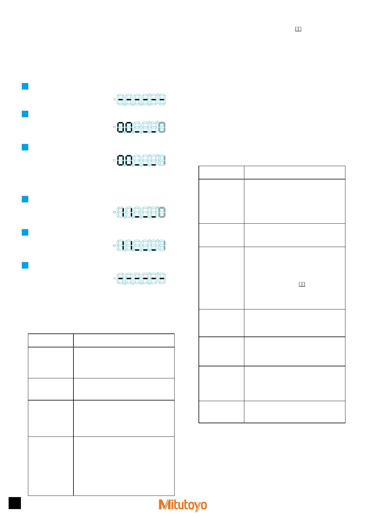
1
Connect the power.
»
The Counter enters the stand-by state.
2
Press and hold [Fn], and then press [P.SET].
»
The Counter enters Parameter mode.
(The set value of parameter number 00
will blink.)
Parameter number Set value
3
Press [P.SET] once to set the value to 1 (parameter setting).
»
Parameters can now be modified. (The
set value remains blinking.)
Parameter number Set value
Tips
If the setting value is 0, you can view the parameter values, but you
cannot change them.
4
Repeatedly press [Fn] to advance the parameter number to 11.
»
The current value of parameter number
11 will blink. (Parameter number 11
sets the Counter direction.)
Parameter number Set value
5
Repeatedly press [P.SET] to set the value to 1 (" - " direction).
»
The value will be set to 1. (The
Counter direction will be set to the " - "
direction.)
Parameter number Set value
6
Press and hold [Fn], and then press [P.SET].
»
The Counter will return to the stand-by
state.
3.2
Basic Parameters
This section explains the basic parameters related to measuring. Be sure to
set these settings before measuring.
Tips
Correct measurement results may not be obtained if the settings are
incorrect.
[Parameter number]
/Setting item
Description
(the values in bold indicate the default value)
[00]
Parameter mode
Used to view or modify parameters.
0: View parameters
1: Set parameters
2: Set an optional constant value*
1
[11]
Counter direction
Sets whether the numeral will increase or decrease
when the spindle of the Linear Gage is pushed in.
0: + direction 1: - direction
[12]
Counting method
Sets the counting method according to the type of
the Linear Gage to be connected.*
2
0: INC
1: ABS
2: Multi-Unit
[15]
Unit system
selection*
3
The unit for displayed values can be set to "mm"
or "E units". E=1/25.4 mm. After the unit is set,
the default value will not be restored even if the
parameters are re-initialized.
0: mm
1: E 5/100,000 reading*
4
2: E 1/10,000 reading*
4
3: mm (when connecting an E gage, 1/10,000
reading)
*
1
The optional constant value setting is available only when the value of
parameter number 16 is set to 3. For details, see
"4.6 Optional Constant
Value Setting" (page 4).
*
2
Select "0: INC" when an INC (incremental) type Linear Gage is connected.
Either "0: INC" or "1: ABS" can be selected when an ABS (absolute) type
Linear Gage is connected.
When "0: INC" is selected:
Count and display the current position of the Linear Gage when starting up
the Counter. Perform Zero setting, etc., when resetting the display value.
When "1: ABS" is selected:
The Counter memorizes the Linear Gage origin (0 point) when starting up
the Counter and displays the counting value from the origin. The origin that
was memorized will be remained even if the Counter is re-started.
When you connect the Multi-Unit, set the value to 2. Do not set the SELECT
switch of the Multi-Unit to "EX".
*
3
The Preset value and tolerance value that had been set will be cleared if the
setting is changed.
*
4
When an E type gage is connected, the minimum reading of the Counter will
be the resolution of the gage.
3.3
Advanced Parameters
This section explains the parameters related to the display, functions, and
external output of the Counter. Configure the settings appropriate to your
application.
[Parameter number]
/Setting item
Description
(the values in bold indicate the default value)
[10]
Parameter
initialization*
1
If you set the value of this parameter to 1, the
set values for all parameters, except for the
unit setting, can be reset to their default values
(initialized).
Once this setting has been enabled, this parameter
is reset so its set value is 0 (do not initialize).
0: Do not initialize 1: Initialize
[14]
Display at startup
Selects stand-by state or Counter display to display
at startup.
0: [------] display 1: 0.000
[16]
Calculation with a
constant
Sets whether to multiply the counter value by a
predetermined factor, by an arbitrary factor, or to
not multiply it.
The value obtained by multiplying the counter
value by the set constant value will be displayed as
the measurement result. For details about optional
constant value setting, see
"4.6 Optional
Constant Value Setting" (page 4).
0: Do not calculate
2: 10 times
1: 2 times
3: Arbitrary value
[17]
Hide the lowest-order
digit
Hides the lowest-order digit.
However, the lowest-order digit will be included in
printouts.
0: Display all digits 1:
Hide the lowest-order digit
[20]
Tolerance judgment/
Digimatic output
switchover
Switches between tolerance judgment result output
and Digimatic output.
0: Tolerance judgment result output
1: Digimatic output
[29]
Digimatic input
WAIT*
2
Sets the wait time for the Digimatic input signal.
Change this when the Counter cannot read the
input signals from a Digimatic device.
0: No wait
2: 400 ms WAIT
1: 200 ms WAIT
[35]
Key protect
Key operations can be disabled to prevent
operation errors.
0:
Key operation enabled
1:
Key operation disabled
*
1
The Preset value and tolerance value that had been set will be cleared if the
setting is changed.
*
2
The display speed can be changed. When you connect the Multi-Unit, set
the value to 1.
 Loading...