R
rachelhernandezJul 26, 2025
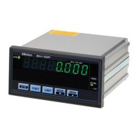
Why is the counter value incorrect on my Mitutoyo Cash Counter?
- Ggary87Jul 26, 2025
If the Mitutoyo Cash Counter displays an incorrect counter value, it might be due to several reasons. First, the parameters might not be correctly set for the type of Linear Gage. Another potential cause is that Peak mode (MAX or MIN is lit) is active; if so, cancel Peak mode. Also, check if the HOLD signal (UNIT is blinking) is being input via the external input. Finally, verify that calculation with a constant function is not active; if it is, cancel it by setting parameter number 41 to 0.