EasyManua.ls Logo

Mitutoyo EH-101P User Manual

Mitutoyo EH-101P
76 pages
To Next Page IconTo Next Page
Page #1 background imageLoading...
Page #1 background image
No. 99MBC109B3
Date of publication: February 1, 2019
(
1
)
User's Manual
- Instructions for use -
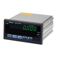
Linear Gage Counter
EH Series
EH-101P
EH-102P
EH-102Z
EH-102S
EH-102D
Read this User's Manual thoroughly before operating
the instrument. After reading, retain it close at hand for
future reference.
This English language version of the User's Manual
contains the original instructions.
*99MBC109B*

Questions and Answers:

Mitutoyo EH-101P Specifications

General IconGeneral
BrandMitutoyo
ModelEH-101P
CategoryCash Counter
LanguageEnglish

Summary

Document Conventions

Safety Warning Conventions

Explains symbols and wording for potential hazards.

Action Conventions

Details symbols for prohibited and mandatory actions.

Referential Information Conventions

Describes symbols for referring to other information or locations.

Safety Precautions

Product Use Precautions

Guidelines for proper handling, application, and general usage of the product.

Installation Environment

Installation Site Requirements

Conditions regarding vibration, dust, sunlight, temperature, and humidity for optimal performance.

Compliance and Export Information

Electromagnetic Compatibility (EMC)

Information regarding the product's compliance with EMC directives.

Export Control and EU Notes

Details on export regulations and requirements for EU member countries.

Product Disposal and Compliance

Disposal of Electrical Equipment

Instructions for disposing of old electrical and electronic equipment.

China RoHS Compliance

Information on the presence of hazardous substances according to China RoHS standards.

Warranty Information

Disclaimer

About This Document

Document Structure and Purpose

Overview of the manual's structure, intended audience, and purpose.

How to Read This Document

Measurement Preparation and Key Terms

Guidance on preparing for measurements, operation keys, and definitions.

1 Overview

Major Functions

Describes the primary functions of the Linear Gage Counter.

Supported Linear Gages

Lists the Linear Gages compatible with the counter and their features.

1 Overview

Part Names and Functions

Identifies and describes the components on the front side of the main body.

1 Overview

Rear Side of the Main Body

Identifies and describes the connectors and controls on the rear side.

1 Overview

Operation Flow

Outlines the basic steps for operating the counter.

2 Setup

Unpacking

Instructions for checking the contents of the product package.

Mounting Procedures

Steps for installing the counter, including panel mounting.

2 Setup

Connections and Power Source

Details on connecting the power source and preparing for external connections.

2 Setup

External Equipment Connections

Procedures for connecting external equipment via various cables.

2 Setup

Operation Check

Steps to verify correct cable connections and initial operation.

3 Setting Parameters

Parameter Setting Procedure

Step-by-step guide to entering Parameter mode and setting basic parameters.

3 Setting Parameters

Basic Parameters

Explanation of fundamental parameters for measurement setup.

3 Setting Parameters

Advanced Parameters

Details on parameters related to display, functions, and external output.

3 Setting Parameters

Display Mode Details (2-Axis Models)

Explains the internal structure of counters and display modes for 2-axis models.

3 Setting Parameters

Display Mode Selection Options

Lists and describes the available display modes based on parameter number 06.

3 Setting Parameters

CEL-Specific Parameters

Parameters that can be set individually for each CEL (internal counter).

3 Setting Parameters

Overview of Setting Parameters

Provides a flowchart and overview of the parameter setting process.

4 Basic Operations

Switching Display A and B

How to select between Display A (upper) and Display B (lower) on 2-axis models.

4 Basic Operations

Switching Displayed Bank

How to switch between BANK1 and BANK2 on 2-axis models.

Zero Setting

Procedure to reset the counter value to zero for each CEL.

4 Basic Operations

Preset Function

How to set an arbitrary preset value for the counter.

4 Basic Operations

Peak Mode Operations

How to switch between normal, max hold, min hold, and TIR measurement modes.

4 Basic Operations

Tolerance Value Setting

How to set 3-step tolerance judgment values for each CEL.

4 Basic Operations

5-Step Tolerance Setting

How to set 5-step tolerance judgment values.

4 Basic Operations

Optional Constant Value Setting

How to apply a multiplication factor to internal counter values.

4 Basic Operations

Memory Management

Procedures for registering, reading, and clearing memory data.

5 External Input/Output Function

Digimatic Output

How to print measurement data using a Digimatic Mini-Processor.

USB Communication

How to connect to a PC for data transfer using SENSORPAK.

5 External Input/Output Function

RS-232C Communication and Connections

Details on connecting and communicating via RS-232C interface.

5 External Input/Output Function

RS-232C Communication Commands

Explains the commands used for remote operation and data manipulation via RS-232C.

5 External Input/Output Function

Parameter Saving and Loading

Procedures for saving and loading counter parameters to/from a PC.

5 External Input/Output Function

RS LINK Function and Connections

How to connect and control multiple counters using the RS LINK function.

5 External Input/Output Function

RS-232C Data Output Duration

Calculation of maximum output duration for RS-232C data commands.

5 External Input/Output Function

I/O Connector Terminal Function and Connections

Details on the I/O connector pin assignments and connection procedures.

5 External Input/Output Function

I/O Output Function

Explains how to output tolerance judgment results and data via the I/O connector.

5 External Input/Output Function

I/O Input Function

How to use external signals to control counter functions like BANK, Peak mode, etc.

5 External Input/Output Function

I/O Timing Chart

Timing diagrams for tolerance judgment and BCD output signals.

6 Troubleshooting

Troubleshooting Guide

Common problems and their solutions for counter operation.

6 Troubleshooting

Error Messages and Codes

Lists and explains various error codes displayed by the counter.

6 Troubleshooting

Error Cancellation Methods

Describes the methods for canceling or resolving error states.

7 Specifications

Basic Specifications

Technical specifications including model numbers, display, reading, power, and dimensions.

7 Specifications

External Dimensions

Drawings and dimensions of the counter unit for all models.

Options

List of available optional parts and accessories for the counter.

Service Network

International Service Centers

Contact information and locations for Mitutoyo service centers worldwide.

Revision History

Related product manuals