4 Basic Operations
30
No. 99MBC109B
2
Press [LIMIT].
»
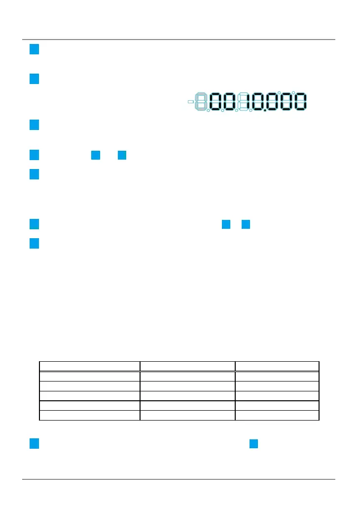
The Tolerance judgment indicator will light in amber. (Tolerance value S1 will be selected.)
3
Press [MODE].
» The input digit will shift to the right.
4
Press [A_ZERO]/[ZERO] or [B_ZERO].
»
The tolerance value will be modied.
5
Repeat steps
3
and
4
until you have set the desired tolerance value.
6
Press [LIMIT].
»
Tolerance value S1 will be applied.
»
The Tolerance judgment indicator will light in red. (Tolerance value S4 will be
selected.)
7
Set the tolerance value S4 in the same steps as in
3
to
5
.
8
Press [LIMIT].
»
The tolerance value S4 will be applied, and the Counter will return to the Counter
display.
Tips
An error will occur unless S1 ≤ S4. Press [SEL]/[CE] to redo the input from S1.
4.6.2 5-Step Tolerance Value Setting (5-Step Tolerance
Zone Selection)
With S1 to S4 set as the tolerance values, the 5-step tolerance judgment will be
performed as follows:
Judgment conditions
Tolerance judgment indicator
I/O output (PIN number)
Measurement result < S1 Amber indicator on AL1 (3) / BL1 (11)
S1 ≤ measurement result < S2 Amber indicator blinks AL2 (4) / BL2 (12)
S2 ≤ measurement result ≤ S3 Green indicator on AL3 (5) / BL3 (13)
S3 < measurement result ≤ S4 Red indicator blinks AL4 (6) / BL4 (14)
S4 < measurement result Red indicator on AL5 (7) / BL5 (15)
This section explains how to set the 5-step tolerance value.
1
Press and hold [SEL]. (For 1-axis models, proceed to step
2
.)
»
The selected Display will blink.