5
Printed in Japan
Date of publication: August 1, 2021 (1)
4
Press [ZERO].
»
The input digit will shift to the right. (The
currently selected digit will blink.)
5
Press [P.SET].
»
The multiplication factor will be
modified.
6
Repeat steps
4
and
5
until you have set the desired tolerance
value.
Tips
The setting range is
±
9.9999.
7
Press and hold [Fn], and then press [P.SET].
»
The Counter will return to the Counter display.
5
External Input/Output Function
This product has an I/O connector that enables data communication with
external equipment. There are 2 types of external output modes: "Tolerance
judgment output mode", which outputs the tolerance judgment result, and
"Digimatic output mode", which outputs data to Digimatic equipment. Also, you
can activate the Preset function and activate HOLD on the counter value through
external signal input.
5.1
Connections
Compatible plug and connecting cable
Compatible plug:
y
MIL type connector FAS-10-17 (YAMAICHI)
y
MIL type connector XG4M-1030-T (OMRON)
Cable: Use shielded wires and limit the connecting cable length to 3 m or less.
Pin assignment
1
2
9
10
Tips
• External input is valid when input voltage is "L". (External input is
negative logic.)
• "I/O" in the following table refers to the first letters of "Input/Output"
respectively. Refer to the input circuit for "I", and the output circuit for
"O".
• In Digimatic output mode, the function of each pin is different. After
setting the output mode, connect the cable.
• The leads at one end of the I/O cable (option) are unbound. Process
them as necessary. Connect the F.G. line (green, with a crimping
terminal) in the cable to the grounding terminal of the main body.
z
Tolerance judgment output mode
Pin
number
I/O Name Function
Option
I/O cable color
1 - COM Internally connected to GND Light brown/
Black
2 O +NG Tolerance judgment result output
y
Relevant output terminal: "L"
y
Output on error: both +NG and
-NG are "L"
Light brown/
Red
Yellow/Black
Yellow/Red
3 O GO
4 O -NG
5 I HOLD HOLD input (Error cancel) Bright green/
Black
6 I P.SET Preset input Bright green/
Red
- - - No connection should be made
other than those shown above.
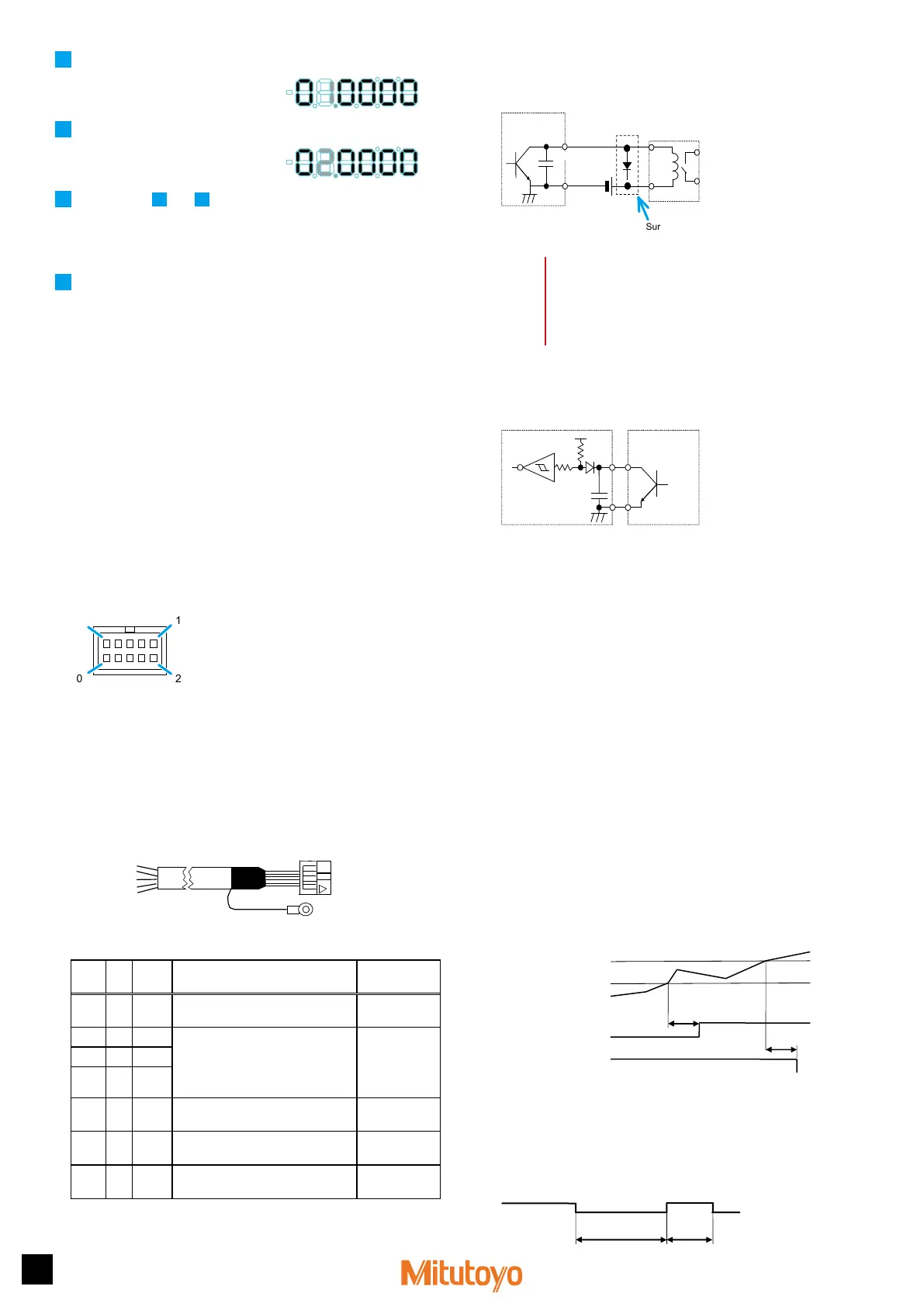
Output circuit
Transistor is on when the output is "L" (open collector).
COM
0.01 µF
Counter
TD62583 equivalent
Output
External
equipment
Reference
circuit
Output withstand voltage: Max. 24 V
Output current: Max. 20 mA
Output saturation voltage: Max. 0.7 V
Surge-current-absorbing diode
60 V 100 mA or more
NOTICE
• When using relays, incorporate a surge-current-absorbing diode
or a protective circuit. If no protection is incorporated, the IC in the
Counter may be damaged.
• The output current when the tolerance judgment result is output is
20 mA at maximum.
Input circuit
Input is valid when the input voltage is "L".
+5 V
5 kΩ
5 kΩ
0.01 µF
Input current: Max. 1 mA
Input voltage: H = 4 to 24 V
L = Max. 1 V
Counter
External
equipment
Reference
circuit
Use open-collector
output or relay
output, etc.
5.2
Digimatic Output Function
Printing by Digimatic Mini-Processor
You can print the measurement data by connecting to a Digimatic Mini-
Processor (DP-1VR). Connect the DP-1VR to the OUTPUT connector (I/
O connector) of the Counter with the optional connection cable (RS LINK/
Digimatic).
Tips
A maximum of 6 digits can be printed. If a Counter display overflow
occurs, the correct value will not be printed. If an overflow occurs, "F"
will be displayed in the most significant digit, e.g., "F0.0005". Modify the
Preset value to output the measurement with the most significant digit
displayed correctly.
Data output by USB Input Tool
Measurement data can be output to a PC by connecting to USB Input Tool.
Tips
For details, see the User's Manual for USB Input Tool.
5.3
Timing Chart
z
Tolerance judgment result output
Max. 100 ms
NG
-NG
Upper specification limit
Lower specification limit
Counter data
Tips
The length of time until the tolerance judgment result output accurately
reflects the counter data depends on the connected equipment. The
length of time "Max. 100 ms" shown in the previous timing chart is valid
if a LGD-type Linear Gage is connected.
z
Preset
Min. 10 ms
Min.
10 ms
 Loading...