2
Printed in Japan
Date of publication: August 1, 2021 (1)
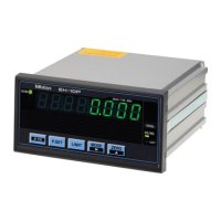
Rear side of the main body
A
B C ED
Symbol
Name Description
A Cable clamp For securing the power cable.
B Linear Gage input connector For connecting a Linear Gage.
C OUTPUT connector (I/O
connector)
For connecting an I/O connecting
cable.
D Grounding terminal For connecting a grounding wire.
E DC jack For connecting the AC adapter.
2
Setup
2.1
Unpacking
When unpacking for the first time, check that the following components are
contained in the box.
Name Q'ty
Linear Gage Counter (this product) 1
Washer (plain washer round, nominal diameter: 4) 6
Rubber foot 4
AC adapter (100 V - 240 V)
06AGC585JA (Japan , USA , Canada,&Co.)
06AGC585D (Germany,&Co.)
06AGC585E (UK,&Co.)
06AEG302DC (China for CCC)
06AGC585K (Korea for KC)
1 of them
User's Manual (this document) 1
Warranty 1
2.2
Mounting on a Panel
Dimensions for the mounting holes in the panel
Width (mm) Height (mm) Panel thickness (mm)
92.0 to 92.8 45.0 to 45.8 1.0 to 3.2
Panel mounting procedure
1
Loosen the fixing bracket mounting screws (see the following
figure), and then remove the fixing brackets.
2
Insert the Counter main body from the front side of the panel.
3
From the back of the panel, reattach the fixing brackets that you
removed in step
1
to the Counter and secure them.
Fixing bracket mounting screws
Fixing brackets
Front side
Rear side
Washers
Tips
Refer to the following table and select the number of washers to use
according to the thickness of the panel.
Panel thickness (mm) 1.0 to 1.3 1.4 to 1.7 1.8 to 2.5 2.5 to 3.2
Number of washers 0 1 2 3
2.3
Attaching Rubber Feet
When placing this product on a desk, attach the supplied rubber feet (4
pieces) to the 4 corners of the bottom surface of the Counter to prevent
slipping and to minimize vibration.
Tips
This product cannot be mounted in a panel with the rubber feet
attached.
2.4
Connections
Power source
Use the supplied AC adapter and the supplied AC cable. If you will not use
the supplied AC adapter, prepare a DC power source (voltage: 9 V to 12 V,
output current: 1 A or more) for each Counter. Solder the power cable to the
terminals of the optional DC plug as shown in the following figure.
- V
+ V
NOTICE
Never use this power source with other electric equipment that runs at a
high voltage and/or large current.
Tips
If you use a commercial power source, use a power cable with a length
of 30 m or shorter. Avoid outdoor wiring.
Connecting cables for external equipment
You must supply an I/O connector connecting cable for connecting external
equipment.
Tips
For details about I/O connecting cables, see "5 External Input/
Output Function" (page 5).
Connection procedure
NOTICE
• When making connections, connect the AC adapter last.
• Do not run the power cable and Linear Gage connecting cable
through a cable duct together with other power lines.
• Secure the power cable and connecting cables for external equipment
to your equipment with a cable tie, cable holder, etc.
Be sure to connect this product to ground. If this product is not grounded,
it will be more susceptible to electrical noise.
Make connections as shown in the figure below.
Linear Gage
input connector
Linear Gage
Grounding terminal
Grounding wire
AC adapter
DC jack
2.5
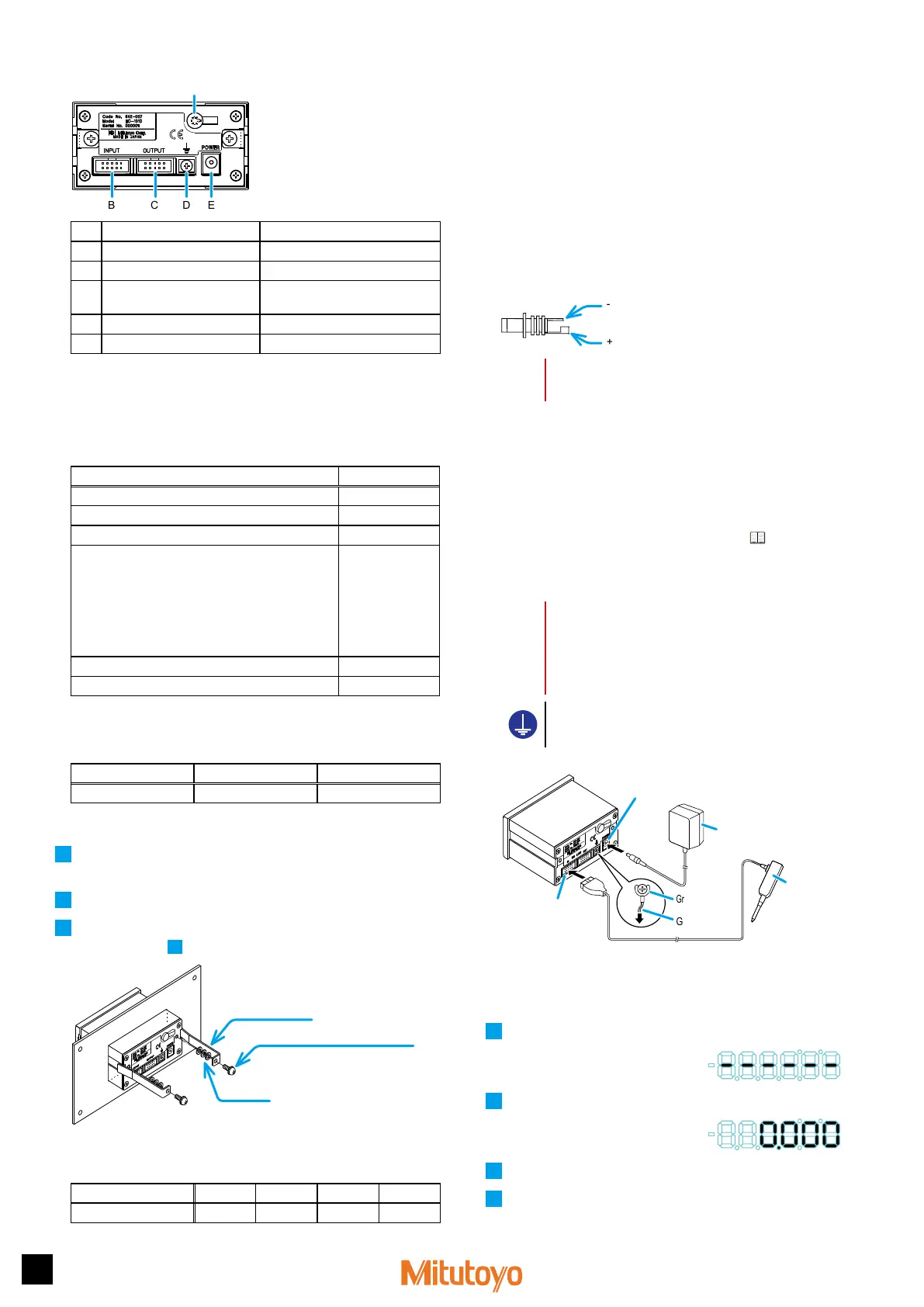
Operation Check
Check the cable connections with the following procedure to confirm that the
connections are correct.
1
Connect the power.
»
The Counter enters the stand-by
state.
2
Press [P.SET].
»
The Counter changes to the
Counter display.
3
Check that the counter value is shown on the Display.
4
Check that the counter value on the Counter changes by moving
the contact point of the Linear Gage up and down.
 Loading...