Fig.
7
4)
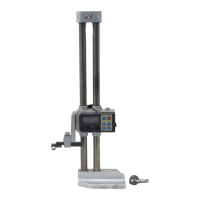
Application
Fig.7(C&L\T, %%h8i>mS$Hl, H2, H3,
&&
To have clear image of ABS and INC modes opera-
Uf.r
?Pl-P3&3!1ST
t6U%%A7&
3.
To
tion, let us take measurements of such
a
workpiece as
shown above for heights HI through H3 and steps PI
throuah P3.
(1)
3.
f.
;r"?%il_TRA(-tz.~A)
&EBS
L
&To
.,
'&$ZONiZ
&
i)
ABS3.Ci.qiZ%UltfU
,&ficfe8$
h
ABS system is used for HI through H3.
d
To
(1) Determine the origin (absolute zero) on the sur-
(2) HI, H2, H3
1:M:X;WllS
L
d
To
&4%?%ifi's>
face plate by turning on the power with the scrib-
a>&!4$fiiS%i;;fihdo
er set on the surface plate.
(2)
Take measurements of HI, H2, and H3 in success-
ion by applying the scriber to the measured point
respectively.
a
~1-~3m;!,tl.l%r21~~;!lli~%~fi~\
3
7,
INC system
is
used for PI through P3.
(1)
~3
74/f&1!ll~i~j0~i:%77
@%-&@
(1) Set the scriber on the measured point
OJ
and
T
1:
INC€- FCZfb
r)
INC;!liE%fii*Utz.r
t-
press the key. The display turns into INC
$;hdT0
mode and INC system
is
reset to zero (floating
zero).
(2)
Set the scriber on the surface
Q
and the display
shows the value of PI.
Press the key here.
(3)
The ,display shows the value of P2 when the scrib-
er
is
set on the surface
@.
In this way, you can
take measurement of P3, too.
(4)
When you press the
key with the scriber set
on the surface
@,
the display turns into
ABS
mode and shows the height H3.
 Loading...