Mitutoyo Corporation 20-1, Sakado 1-Chome, Takatsu-ku, Kawasaki-shi, Kanagawa 213-8533, Japan
Date of publication: December 1, 2021
Printed in Japan
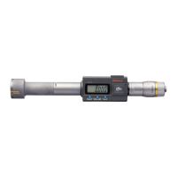
1. Names of Components
④
⑤
⑥
⑨
⑩
⑪⑫
⑬
⑦
⑧
③
① Measuring head
② LCD body
③ Display unit
④ Contact point
⑤ Connection area
⑥ Display unit (LCD)
⑦ Output connector
⑧ Cover
⑨ Sleeve
⑩ Ratchet
⑪ Thimble
⑫ Setting screw
⑬ Battery compartment cover
■
Display unit (LCD)
⑱
⑲
⑳
⑮
⑯
⑰
⑭
⑭ [HOLD] key
⑮ [ZERO/ABS] key
⑯ [PRESET] key
⑰ [in/mm] key (in/mm products only)
⑱ Sign display
⑲ Function Lock display
⑳ Hold display
㉑ Low voltage display
㉒ INC display
㉓ Preset display
㉔ Unit display
2. Installing the Battery
When attaching the battery compartment cover, be sure to attach the gasket properly. The product
may display an error or malfunction if the battery compartment cover or gasket is not mounted
correctly.
Tips
• Be sure to use SR44 (silver oxide button battery part No. 938882) for the battery.
• Do not rotate the thimble until the count is displayed. Initial setting of the electrical components
may fail, or the product may not count normally. If you mistakenly move the thimble, reinstall the
battery.
• The battery supplied is for confirming the functions and performance of the product. Note that
this battery may not fulfill the predetermined life.
• Malfunction or damage due to depleted batteries, etc. is not covered by the warranty.
• Follow local rules and regulations regarding battery disposal.
The battery is not installed into the product at purchase. Install the battery as follows.
1
Use the supplied Phillips screwdriver (No.05CAA952) to loosen and remove the battery
compartment cover fixing screws (M1.7 x 0.35 x 4/No.04AAB541).
2
If replacing an existing battery, remove the old battery.
3
Insert the battery (SR44) with the positive side facing upward.
Confirm that the gasket (No.05SAA372) is installed correctly in the proper position.
4
Place the battery compartment cover over the battery compartment and hold down the edge by
hand while making sure there is no gap between the cover and body, and then tighten it using
the screws.
》 The "- - - - - -" display blinks.
5
Press the [PRESET] key.
》 Count display appears and counting starts.
4
5
①
+ -
+ terminal
- terminal
SR44
②
SR44
Tips
• Re-installing the battery will erase the PRESET value (reference point) position. Perform
reference point setting again (refer to "4. Reference Point Setting").
• If an abnormal display is shown, such as an error display or not counting, etc., try removing the
battery and reinstalling.
Safety Precautions
To ensure operator safety, use this product in conformance with the directions, functions
and specifications given in this User's Manual.
Use under other conditions may compromise safety.
• Always keep batteries out of reach of children, and if swallowed, consult a physician
immediately.
• Batteries should never be short-circuited, disassembled, deformed or come in contact with
extreme heat or flames.
• If battery alkaline liquid comes in contact with the eyes, flush eyes immediately with clean
water and consult a physician. If battery alkaline liquid comes in contact with the skin,
flush the exposed area thoroughly with clean water.
• Never attempt to charge the primary battery or reverse the positive-negative terminals
when mounting. Improper battery handling or mounting may cause the battery to explode,
cause battery leakage and/or serious bodily injury or malfunctioning.
• Always handle the sharp measuring faces of this product with care to avoid injury.
• Do not disassemble or modify.
• Do not use or store the product in a place with sudden temperature changes. Adapt the
product to ambient temperature before use.
• Do not store the product in a place with high humidity or a lot of dust.
• Firmly close the battery compartment cover if the product is used in a place where it is
directly exposed to splashes of coolant, etc. When mounting the output cable and cover,
firmly tighten the fixing screws so that there is no gap. As well, clean and apply anti-rust
treatment after use. Rust may cause malfunction.
• Do not use even waterproof types submerged, as coolant ingress cannot be completely
prevented. Complete prevention of coolant ingress, etc., may also not be possible if the
product is used in locations exposed to direct jets of liquid.
• Do not apply excessive force or subject to sudden impacts such as dropping.
• If oil or cutting chips become attached to the sliding portion of the contact point, a
malfunction may result. Wipe off any oil or cutting chips after use.
• When cleaning, wipe this product with a soft cloth moistened with diluted neutral
detergent. Do not use an organic solvent such as thinner, which may cause the product to
deform or malfunction.
• Do not write numbers, etc. with an electric pen.
• If the product is to be out of use for three months or more, remove the battery before storage.
Liquid leakage from the battery may damage the product.
• Do not pry out or suspend the product while it is inserted inside the workpiece.
• Use the product only with the supplied contact point.
• Do not remove the contact points; otherwise damage may result.
Digimatic Holtest
HTD-R
User's Manual
No. 99MAB026A1
=
> 2 s
=
< 1 s
Key operation icon
Contents
1. Names of Components ...........................................................................................Page 1
2. Installing the Battery ...............................................................................................Page 1
3. Precautions for Use ................................................................................................Page 2
4. Reference Point Setting ..........................................................................................Page 2
5. Measurement Method .............................................................................................Page 2
6. Key Functions .........................................................................................................Page 2
7. Function Lock Function (Preventing Accidental Operation) ....................................Page 2
8. Errors and Troubleshooting.....................................................................................Page 3
9. Installation/Removal Method for Measuring Head and Extension Rod...................Page 3
10. Specifications ..........................................................................................................Page 3
11. Output Function ......................................................................................................Page 3
12. Options....................................................................................................................Page 3
13. Off-Site Repairs (Subject to Charge) ......................................................................Page 3
1