Mitutoyo Corporation 20-1, Sakado 1-Chome, Takatsu-ku, Kawasaki-shi, Kanagawa 213-8533, Japan
Date of publication: December 1, 2021
Printed in Japan
8. Errors and Troubleshooting
• " " display
The battery voltage is low. Replace the battery promptly.
• "Err-oS" display
A counting error has occurred due to excessive speed or noise. Try removing the battery and
reinstalling.
• "Err-S" display
Initial setting of the electrical components failed, or a counting error has occurred due to a sensor
signal error. Try removing the battery and reinstalling.
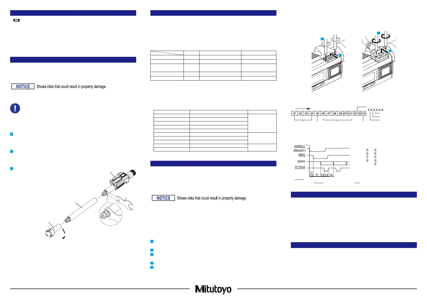
9. Installation/Removal Method for Measuring Head and Extension Rod
For interchangeable-head sets, it is necessary to replace the measuring head according to the size of
the workpiece.
An extension rod (optional for models other than interchangeable-head sets) can be used to measure
deep holes.
Do not hold the display unit while using the wrench to loosen or tighten the connection area.
Otherwise, damage may result.
• Be sure to set the reference point after installing or removing the measuring head or
extension rod.
• Do not misassemble the measuring head and display unit (for models other than the
interchangeable-head sets). These parts are incompatible and accuracy cannot be
guaranteed if they are used.
Use the following procedure to install and remove the measuring head and extension rod.
1
Set the supplied wrench to the groove in the
connection area. Fix the display unit in place
while rotating the measuring head by hand to
detach it.
2
To replace the measuring head, use the
wrench to hold the display unit in place,
replace the measuring head, and then rotate
the new head by hand to tighten it.
3
To install the extension rod, use the wrench
to hold the display unit in place, and then turn
the extension rod and then the measuring
head (in that order) by hand to tighten
them.
Use the same procedure to remove the
extension rod.
Display unit
Measuring head
Extension rod
Wrench
Loosen
10. Specications
■
Common Specications
Display : LCD (6-digit and minus sign)
Power supply : Button type silver-oxide battery (SR44 No.938882), x1
Battery life : 1.2 years
Operating temperature : 5 °C to 40 °C
Storage temperature : -10 °C to 60 °C
Standard accessories :
Single item Non-interchangeable-head sets Interchangeable-head sets
Wrench
P P P
Hex wrench
P P P
Phillips screwdriver
(No.05CAA952)
P P P
Setting ring -
P P
Extension rod - -
P
IP protection level :
IP65 (refer to IEC60529 for details).
Dust-proof (level 6) : No ingress of dust allowed.
Protection against water jets (level 5) : Protects the equipment against water jets from any direction.
■
Individual Specications
Maximum measuring length
Maximum permissible error
J
MPE
*1
Resolution
8 - 12 mm
± 2 µm (maximum difference 2 µm)
0.001 mm
16 - 63 mm
± 3 µm (maximum difference 3 µm)
75 - 100 mm
± 4 µm (maximum difference 4 µm)
125 - 200 mm
± 5 µm (maximum difference 5 µm)
225 - 300 mm
± 6 µm (maximum difference 6 µm)
0.35 - 0.5 in ± 0.0001 in (maximum difference 0.0001 in)
0.00005 in0.65 - 2.5 in ± 0.00015 in (maximum difference 0.00015 in)
3 - 4 in ± 0.0002 in (maximum difference 0.0002 in)
5 - 8 in ± 0.00025 in (maximum difference 0.00025 in)
0.0001 in
9 - 12 in ± 0.0003 in (maximum difference 0.0003 in)
*1: Maximum permissible error for indicated value via contact with full measuring face
J
MPE (20 °C).
11. Output Function
■
Display Value External Output
The display value can be output to a device by connecting the product and the external device with
a connection cable (option).
■
Connection Cable Installation Method
• Always use the 0-size Phillips screwdriver (No.05CZA619) supplied with the connection cable
(option) when installing/removing screws, and tighten to a torque of 5 to 8 cN・m or so.
Otherwise, it may cause damage.
• When connecting the connection cable, ensure that the connector gasket does not protrude.
If the connector gasket is not installed properly, waterproof functionality may decrease and lead
to malfunctions.
•
When connecting the connection cable, pay attention to the connector direction.
Otherwise, damage may result.
1
Use the Phillips screwdriver supplied with the connection cable to remove the cover fixing screws
(M1.7 x 0.35 x 2.5, No.04AAB543).
2
Remove the cover.
3
Check that the connector gasket (No.09GAA374) is correctly installed at the proper position
(do not remove the connector gasket).
4
Mount the connection cable plug.
5
While holding in the connection cable plug by hand, tighten the fixing screws.
Tips
•
Ensure that there is no gap between the connection cable plug and the body connector.
• Held display values (refer to "6. Key Functions ■ [HOLD] Key") will be released if output to an
external device.
4
1
5
2
■
Output Data Format
(1)
Output order
(2) All "F"
(3) Sign
(4)
Measured value
(5)
Decimal point
(6) Unit
■
Timing Chart
200 ms
0.14 ms (Typ:0.122 ms)
0.14 ms (Typ:0.122 ms)
0.27 ms (Typ:0.244 ms)
80 ms
0 ms
0.11 ms
0.11 ms
0.22 ms
T1
T2
T3
T4
T5
*1: DATAsw is LOW while the data output key is being pressed.
*2: The time T5 until DATAsw goes to the LOW level and REQ is input is determined by the data processing
device performance.
12. Options
• Connection cable (1 m) : No.05CZA662
• Connection cable (2 m) : No.05CZA663
• Extension rod
Length 100 mm, measuring range 6 mm to 12 mm (0.275 in to 0.5 in) : No.952322
Length 150 mm, measuring range 12 mm to 20 mm (0.5 in to 0.8 in) : No.952621
Length 150 mm, measuring range 20 mm to 50 mm (0.8 in to 2 in) : No.952622
Length 150 mm, measuring range 50 mm to 300 mm (2 in to 12 in) : No.952623
For options other than the above, refer to the General Catalog.
13. O-Site Repairs (Subject to Charge)
Off-site repair (subject to charge) is required in the case of the following malfunctions. Contact your
nearest dealer or our sales office.
• The operation of the contact point is poor and the thimble rotation is sluggish.
Operation will worsen if there is oil or rust on the sliding portion of the contact point.
(1)
MSD LSD
(5)
(2)
(1111)
(4)
(3)
+:0(0000)
–:8(0001)
3(1100)
4(0010)
5(1010)
(6)
mm:0(0000)
in:1(1000)
3
 Loading...