Mitutoyo Corporation 20-1, Sakado 1-Chome, Takatsu-ku, Kawasaki-shi, Kanagawa 213-8533, Japan
Date of publication: December 1, 2021
Printed in Japan
3. Precautions for Use
■
Measuring Force
• Use the ratchet to ensure consistent measuring force.
• The appropriate measuring force is achieved with the following procedure: make light contact
between the measurement surfaces and the workpiece, stop momentarily, and then manually turn
the ratchet about five to six times. Note that excessive measuring force may cause errors.
■
Precautions after Use
• After use, clean the entire product and check that none of the parts are damaged.
•
If using in places exposed to water-based cutting fluid, always apply anti-rust treatment after cleaning.
• If the product is to be out of use for three months or more, remove the battery before storage.
4. Reference Point Setting
Set an arbitrary preset value (reference point registration) prior to setting the reference point (reference point setting).
•
Be sure to follow the procedure below to confirm and set the reference point prior to measuring.
•
When setting the reference point for this product, make sure to use a calibrated gage (setting ring, etc.).
• Remove any dirt or oil from the measuring surfaces of the gage and product prior to
setting the reference point.
• Due to the product mechanism, the measured value will differ depending on whether
the entire surface of the contact point or only its edge is used for measurement. When
measuring, use the same conditions when setting the reference point.
• Use the same orientation and conditions when measuring and setting the reference
point. (Refer to Figure 1 if measuring with the contact point edge in a blind hole.)
Do not ground the bottom of the measuring head when setting the reference point or
measuring (Figure 2).
Figure 1
Reference point setting
Workpiece
Figure 2
1) Reference point registration
Register (preset) the gage dimensions to the product. Two preset values (P1 and P2) can be
registered to the product.
Tips
Press and hold the [HOLD] key to switch between P1 and P2.
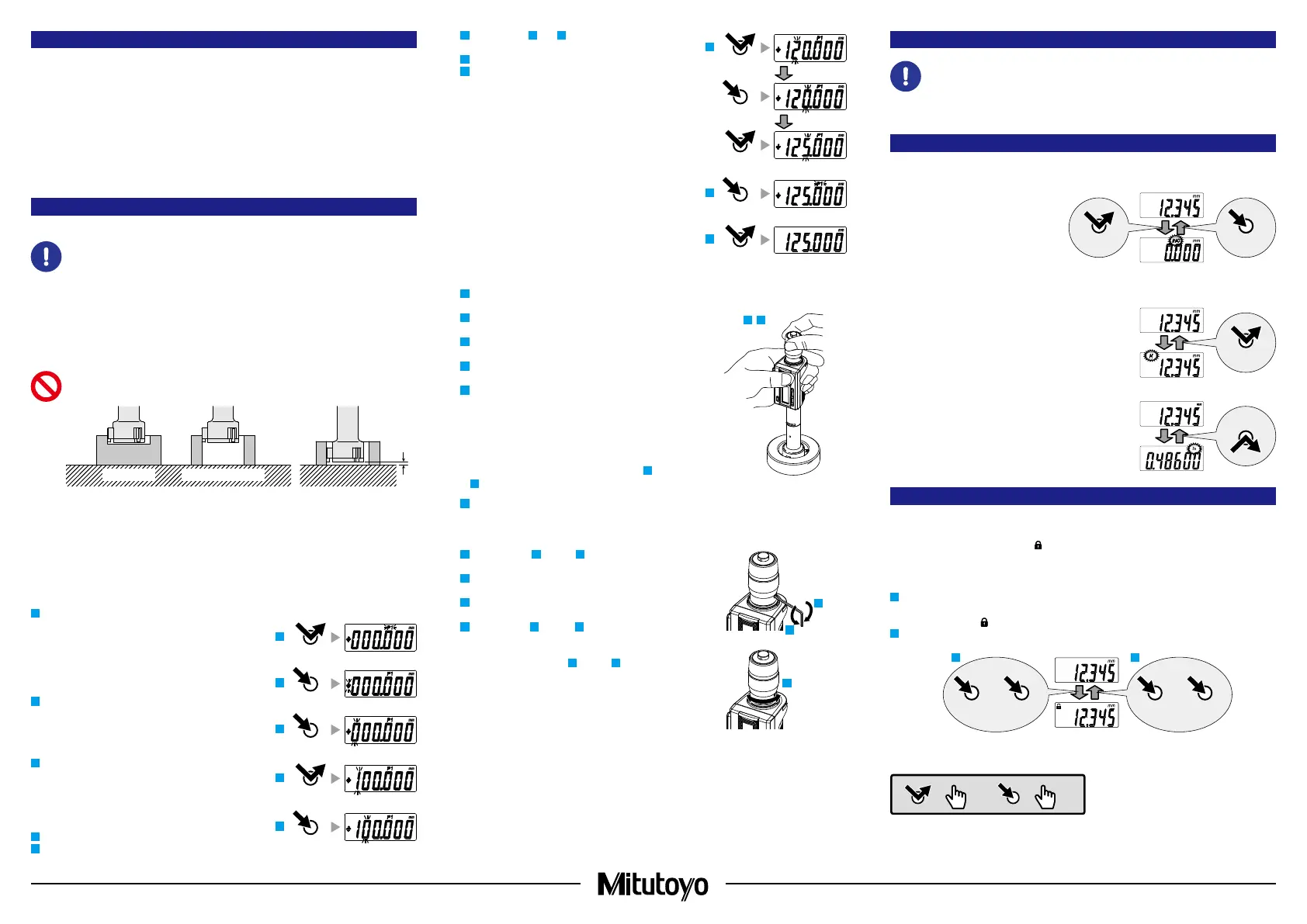
<Example> Registering 125.000 mm to P1
1
Briefly press the [PRESET] key.
》
The previously registered number is displayed and "P1" blinks.
Tips
•
Zero will be displayed immediately after replacing the battery.
• If "P2" is blinking, press and hold the [HOLD] key to
cause "P1" to blink.
2
Press and hold the [PRESET] key.
》 The sign blinks.
Tips
Briefly press the [PRESET] key to switch between "+" and "-".
3
Press and hold the [PRESET] key.
》 The number on the left blinks.
Tips
The numbers will switch in order from "0" to "1" to "2" up to "9"
and then "0" each time the [PRESET] key is briefly pressed.
4
Briefly press the [PRESET] key until "1" is displayed.
5
Press and hold the [PRESET] key.
》 The number in the next digit blinks.
3
5
4
2
1
PRESET
PRESET
PRESET
PRESET
PRESET
6
Repeat steps
4
and
5
, so that "2," "5," and "0" are
displayed in each digit.
7
Press and hold the [PRESET] key until "P1" blinks.
8
Briefly press the [PRESET] key.
》 "P1" goes out and registration is complete.
2) Reference point setting
1
Remove any dirt or dust from the measuring surfaces of
the gage and the product.
2
Set the dimension of the product slightly smaller than
that of the gage, and then slowly insert it into the gage.
3
Rotate the thimble and bring the contact points gently
into contact with the inside of the gage.
4
Rotate the ratchet five to six times to apply the proper
measuring force.
5
Briefly press the [PRESET] key.
》 "P1" or "P2" blinks, and the registered preset value
(zero if not registered) is displayed.
Tips
• Press and hold the [HOLD] key to switch between P1
and P2.
• To change the preset value, refer to steps
2
through
8
in "1) Reference point registration".
6
Briefly press the [PRESET] key.
》 "P1" or "P2" goes out.
To use thimble graduations as well, set using the procedure
below.
7
Perform steps
1
through
4
, and then use the supplied
hex wrench to loosen the setting screw.
8
Slightly rotate the sleeve and align it with the proper
indicated value.
9
Use the supplied hex wrench to tighten the setting
screw and fix the sleeve.
10
Perform steps
1
through
4
, and confirm that the proper
number is displayed.
If the proper number is displayed, setting is complete. If it is
not displayed, repeat steps
7
through
9
.
Tips
• The display of this product automatically turns off if not
used for 20 minutes or more. To display again, either
rotate the thimble or press the [ZERO/ABS] key.
• If the [PRESET] key is accidentally pressed during
measurement, press the [ZERO/ABS] key to return to
the former state. If this does not enable the product to
recover, perform the reference point setting procedure
once more.
• Once the product has been inserted, do not move it
until the reference point has been set.
2 3
7
8
9
5. Measurement Method
Be sure to perform reference point setting before measurement.
Using the same orientation and procedure used during reference point setting, insert the product
into the workpiece, and then read the display value.
6. Key Functions
■
[ZERO/ABS] Key
• Briefly press the [ZERO/ABS] key.
》 "INC" is displayed, and the display
is set to zero.
• Press and hold the [ZERO/ABS] key
(for at least 2 seconds).
》
"INC" goes out, and the length from
the reference point (anvil measuring
surface) is displayed.
■
[HOLD] Key
• Press the [HOLD] key.
》 "H" is displayed, and the display value is held.
Press the key again to stop holding the value.
■
[in/mm] Key (in/mm products only)
• Press the [in/mm] key.
》 "in" and "mm" switch back and forth each time
the key is pressed.
7. Function Lock Function (Preventing Accidental Operation)
This product has the Function Lock function, which disables the PRESET function and ZERO/ABS
function in order to avoid accidental changes to the reference point position.
Setting the Function Lock causes [
] on the LCD to light up and disables the [PRESET] key,
[ZERO/ABS] key, and [in/mm] key (in/mm products only), with only the hold operation function
enabled.
1
First press and hold the [HOLD] key, and then additionally press and hold the [ZERO/ABS] key
(for at least 2 seconds).
》 [H] display and [
] display light up in sequence ([H] turns off first).
2
Perform the same operation to release the Function Lock.
21
+
ZERO/ABSHOLD
+
ZERO/ABSHOLD
=
> 2 s
=
< 1 s
Key operation icon
ZERO/ABS ZERO/ABS
HOLD
in / mm
6
7
8
PRESET
PRESET
PRESET
PRESET
2
 Loading...