*~a>tt:h2*39trzf'5-;7F*y3
5
~7~u-k
>yV(DP-l.DP-2%) %$#EL
ddZ.
%-fga>f'-
9
&T!PbcqEiTftE
Z
fb
r)
3
f.
~FlJZi&a>EP~
GEa>t?Z
Ir
&~~lJZili6zmEp'fl
ifE;t;t-;R3$-ilizzm
EP%
n
:
;!3qZf'-9B
MAX
MIN
:
@/I\{&
R
:
b>-5
2
:
Fmig
0
:
tE*tE%
tb&.
:T$EBI~~~~U
+
*'Y
Y-~>~+x~;#E!AsQ~wB
L-C
<
tYSL\,
DP- 1 m)B%;#sa@N0.4166
DP-
2 @!+Xt;#flAgN0.4209
DL- 10 R?.+R1#f3a@N0.4212
DT-
10
m+a%fla%~0.4227
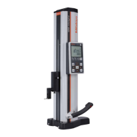
Following data processing becomes possible when
a
Digimatic Mini-Processor (DP-1 or DP-2 etc.) is con-
nected to the output connector of the height gage.
.
Printing of measurement data
.Tolerance limits setting and printing of tolerancing
results
.Statistical operation and printing
n: number of data items
MAX: maximum value of measurements
MIN: minimum value of measurements
R:
range
-
X:
mean value
a:
standard deviation
Plotting histogram
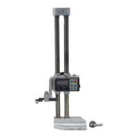
<Connection>
A
processor can be connected to the input connector
of a height gage with a specific cable(option). (A dust
cap attached on the input connector must be remov-
ed first.)
Turn off the processor and the height gage before
connection. Save the dust cap.
<Measurement
data
entry>
Measurement data output to the processor
is
effected
in either of the four methods
:
(Q
by pressing button switch on the connecting cable
@
by pressing the
lonrn/
key of the processor
@
by touch signal of the probe
@
by pressing a foot switch connected to the pro-
cessor DP-1 or DP-2
.For details of processor, refer to the respective
operation manual.
Manual No. 41
66
for DP-1
Manual No. 4209 for DP-2
Manual No. 4212 for DL-10
Manual No. 4227 for DT-10
 Loading...