Mitutoyo Corporation 20-1, Sakado 1-Chome, Takatsu-ku, Kawasaki-shi, Kanagawa 213-8533, Japan
Date of publication: December 1, 2021
Printed in Japan
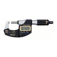
1. Names of Components
0
-
1”
0.001
mm
.00005”
⑧
⑨
⑩
④③②①
⑤ ⑥ ⑦
0
-
1”
0.001
mm
.00005”
⑪
①
Anvil
②
Spindle
③
Swivel clamp
(locks the spindle to prevent motion)
④
Display unit (LCD)
⑤
Sleeve
⑥
Thimble ratchet
(constant pressure device built-in)
⑦
Speeder ratchet
(constant pressure device built-in)
⑧
Cover (type with output only)
⑨
Data output connector
(type with output only)
⑩
Battery compartment cover (at rear)
⑪
Waterproof mark
■ Display Unit (LCD)
⑫⑬
⑮
⑭
⑯
⑰
⑱
⑲
⑳
⑫
[HOLD] key
⑬
[ZERO/ABS] key
⑭
[in/mm] key (in/mm products only)
⑮
[ORIGIN] key
⑯
Sign display
⑰
Function Lock display
⑱
Hold display
⑲
Low voltage display
⑳
INC display
㉑
Preset display
㉒
Unit display
2. Installing the Battery
Always align the battery compartment cover with the threads and install so that the seal does not
protrude. The product may display an error or malfunction if the battery compartment cover or
seal is not mounted correctly.
Tips
• Be sure to use SR44 (silver oxide button battery Part No. 938882) for the battery.
• Do not rotate the ratchet until the count is displayed. Initial setting of the electrical components
may fail, or the product may not count normally. If you mistakenly move the ratchet, reinstall the
battery.
• The battery supplied is for confirming the functions and performance of the product. Note that
this battery may not fulfill the predetermined life.
• Malfunction or damage due to depleted batteries, etc. is not covered by the warranty.
• Follow local rules and regulations regarding battery disposal.
The battery is not installed into the product at purchase. Install the battery as follows.
1
Insert a coin or similar object into the groove on the battery compartment cover, and turn it to
the left to remove the cover.
2
Install the battery (SR44) with the positive side facing up.
3
Position the battery compartment cover and rotate clockwise to attach.
4
Press the [ORIGIN] key.
》 Count display appears and counting starts.
Moving on, set the ORIGIN (reference point) (refer to "4. ORIGIN (Reference Point) Setting").
SR44
1 2 3
4
ORIGIN
Seal
Tips
• Re-installing the battery will erase the ORIGIN (reference point) position. Perform reference
point setting again (refer to "4. ORIGIN (Reference Point) Setting").
• If an abnormal display is shown, such as an error display or not counting, etc., try removing the
battery and reinstalling.
Safety Precautions
To ensure operator safety, use this product in conformance with the directions, functions
and specifications given in this User's Manual.
Use under other conditions may compromise safety.
•
Always keep batteries out of reach of children, and if swallowed, consult a physician immediately.
• Batteries should never be short-circuited, disassembled, deformed or come in contact with
extreme heat or flames.
•
If battery alkaline liquid comes in contact with the eyes, flush eyes immediately with clean
water and consult a physician. If battery alkaline liquid comes in contact with the skin,
flush the exposed area thoroughly with clean water.
• Never attempt to charge the primary battery or reverse the positive-negative terminals
when mounting. Improper battery handling or mounting may cause the battery to explode,
cause battery leakage and/or serious bodily injury or malfunctioning.
• Always handle the sharp measuring faces of this product with care to avoid injury.
• Do not disassemble or modify.
• Do not use or store the product in a place with sudden temperature changes. Adapt the
product to ambient temperature before use.
• Do not store the product in a place with high humidity or a lot of dust.
• Firmly close the battery compartment cover if the product is used in a place where it is
directly exposed to splashes of coolant, etc. For the type with output, when mounting the
output cable and cover, firmly tighten the fixing screws so that there is no gap. As well,
clean and apply anti-rust treatment after use. Rust may cause malfunction.
• Do not use submerged, as coolant ingress cannot be completely prevented. Complete
prevention of coolant ingress, etc., may also not be possible if the product is used in
locations exposed to direct jets of liquid.
• Do not apply excessive force or subject to sudden impacts such as dropping.
• Remove dust, cutting chips, etc. before and after use.
• When cleaning, wipe this product with a soft cloth moistened with diluted neutral
detergent. Do not use an organic solvent such as thinner, which may cause the product to
deform or malfunction.
• Rotating the thimble once will move the spindle 2 mm. Because the spindle moves quickly,
do not allow it to make violent contact with the measuring surface when measuring or
during reference point setting.
• The spindle structure prevents pulling out, so do not try to forcibly retract in excess of the
measurement range.
• Dirt on the spindle may lead to malfunction. If the spindle becomes dirty, wipe it clean with
a cloth containing a small amount of alcohol and apply a small amount of micrometer oil
(Part No. 207000).
• If Micrometer Oil is not available and you must use a commercially available product, we
recommend using an anti-rust agent with low viscosity almost equivalent to ISO VG10.
• Do not write numbers, etc. with an electric pen.
• If the product is to be out of use for three months or more, remove the battery before
storage. Liquid leakage from the battery may damage the product.
QuantuMike
MDE-MX/PX
User's Manual
No. 99MAB044A2
Key operation icon
=
> 2 s
=
< 1 s
1
Contents
1. Names of Components ............................................................................................ Page 1
2. Installing the Battery ................................................................................................ Page 1
3. Precautions for Use ................................................................................................. Page 2
4. ORIGIN (Reference Point) Setting .......................................................................... Page 2
5. Measurement Method ............................................................................................. Page 2
6. Key Functions .......................................................................................................... Page 2
7. Function Lock Function (Preventing Accidental Operation) .................................... Page 2
8. Errors and Troubleshooting ..................................................................................... Page 2
9. Specifications .......................................................................................................... Page 3
10. Output Function (Function for Type with Output Only) ............................................ Page 3
11. Options .................................................................................................................... Page 3
12. Off-Site Repairs (Subject to Charge) ....................................................................... Page 3