Mitutoyo Corporation 20-1, Sakado 1-Chome, Takatsu-ku, Kawasaki-shi, Kanagawa 213-8533, Japan
Date of publication: December 1, 2021
Printed in Japan
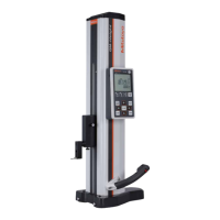
3. Precautions for Use
■ Measuring Force
• Make sure to use the thimble ratchet or speeder ratchet to
ensure consistent measuring force.
• The appropriate measuring force is achieved with the
following procedure: make light contact between the
measurement surfaces and the workpiece, stop
momentarily, and then manually turn the thimble ratchet or
speeder ratchet about three to five times.
• Rotating the thimble once will move the spindle 2 mm.
Because the spindle moves quickly, be sure to make
contact slowly and gently with the measuring surface when
measuring or during reference point setting.
■ Precautions for Measurement
• Use caution when measuring magnetized workpieces. If the product becomes magnetized,
measurement results may be affected.
■ Precautions after Use
• After use, clean the entire product and check that none of
the parts are damaged.
If using in places exposed to water-based cutting fluid,
always apply anti-rust treatment after cleaning.
• For storage, leave a gap of 0.2 to 2 mm open for the
measurement surfaces, and release the swivel clamp.
• If the product will not be used for three months or longer,
apply micrometer oil (Part No. 207000) to the spindle to
prevent rust, and store it with its battery removed.
• If Micrometer Oil is not available and you must use a commercially available product, we
recommend using an anti-rust agent with low viscosity almost equivalent to ISO VG10.
4. ORIGIN (Reference Point) Setting
Reference point setting and measurement should be made in the same orientation
and conditions with the procedure as below.
■ ORIGIN (Reference Point) Setting
1
Clean both anvil and spindle measurement surfaces, together with the gage if it is used, to
remove all debris or dust.
2
For 0 to 25 mm measurement range:
After making light contact with both measurement surfaces, stop momentarily, and then apply
the appropriate measuring force (refer to "■ Measuring Force" in "3. Precautions for Use").
For above the 0 to 25 mm measurement range:
After clamping the gage between the measuring surfaces, bring the spindle into light contact
with the gage, stop momentarily, and then apply the appropriate measuring force (refer to
"■ Measuring Force" in "3. Precautions for Use").
Use a periodically inspected (calibrated) gage (gauge block, setting standard for
outside micrometer, etc.).
3
Press the [ORIGIN] key.
》 Check that [P] is blinking and the ORIGIN (reference point) value* is displayed (*refer to
"Tips" below).
4
Press the [ORIGIN] key again.
》 [P] goes out and the ORIGIN (reference point) value is set.
• For 0 to 25 mm measurement range:
3 4
ORIGIN ORIGIN
2
1
0
-
1”
0.001
mm
.00005”
• For above the 0 to 25 mm measurement range (e.g., 25 to 50 mm):
3 4
ORIGIN ORIGIN
1
2
1
-
2”
0.001
mm
.00005”
Tips
• The display of this product automatically turns off if not used for 20 minutes or more. To display
again, either rotate the ratchet or press the [ZERO/ABS] key.
•
If the [ORIGIN] key is accidentally pressed while making a measurement, press the [ZERO/ABS]
key to return to the former state. If this does not enable the product to recover, perform
"4. ORIGIN (Reference Point) Setting" once more.
• The following table shows the relationship between measurement range and ORIGIN (reference
point) value.
Measuring range ORIGIN (reference point) value Measuring range ORIGIN (reference point) value
0 - 25 mm 0.000 mm 0 - 1 in 0.00000 in
25 - 50 mm 25.000 mm 1 - 2 in 1.00000 in
50 - 75 mm 50.000 mm 2 - 3 in 2.00000 in
75 - 100 mm 75.000 mm 3 - 4 in 3.00000 in
■ Using a Reference Gage other than the Setting Standard for Outside
Micrometer (Standard Accessory)
First set the ORIGIN (reference point) using the standardly equipped setting standard for outside
micrometer.
1
Turn the ratchet until the target value is displayed, and then press the [HOLD] key to hold the value.
2
Press the [ORIGIN] key.
》 [P] blinks.
3
Clamp the reference object and apply the appropriate measuring force with the constant
pressure device (refer to "■ Measuring Force" in "3. Precautions for Use").
4
Press the [ORIGIN] key again.
》 [P] goes out and setting is complete.
ORIGIN
ORIGIN
HOLD
1 2
3 4
1
-
2”
0.001
mm
.00005”
1
-
2”
0.001
mm
.00005”
Tips
To return to the default ORIGIN (reference point) value, reinstall the battery.
Key operation icon
=
> 2 s
=
< 1 s
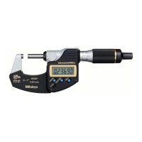
5. Measurement Method
• Be sure to perform reference point setting before measurement.
• Bring the measuring surface of the spindle slowly into contact with the workpiece.
Moving too quickly could deform the workpiece and affect measurement results.
Gradually and lightly bring the measurement surfaces into contact with the workpiece in the same
orientation and conditions as for reference point setting, apply the appropriate measuring force,
and then read the display value (refer to "■ Measuring Force" in "3. Precautions for Use").
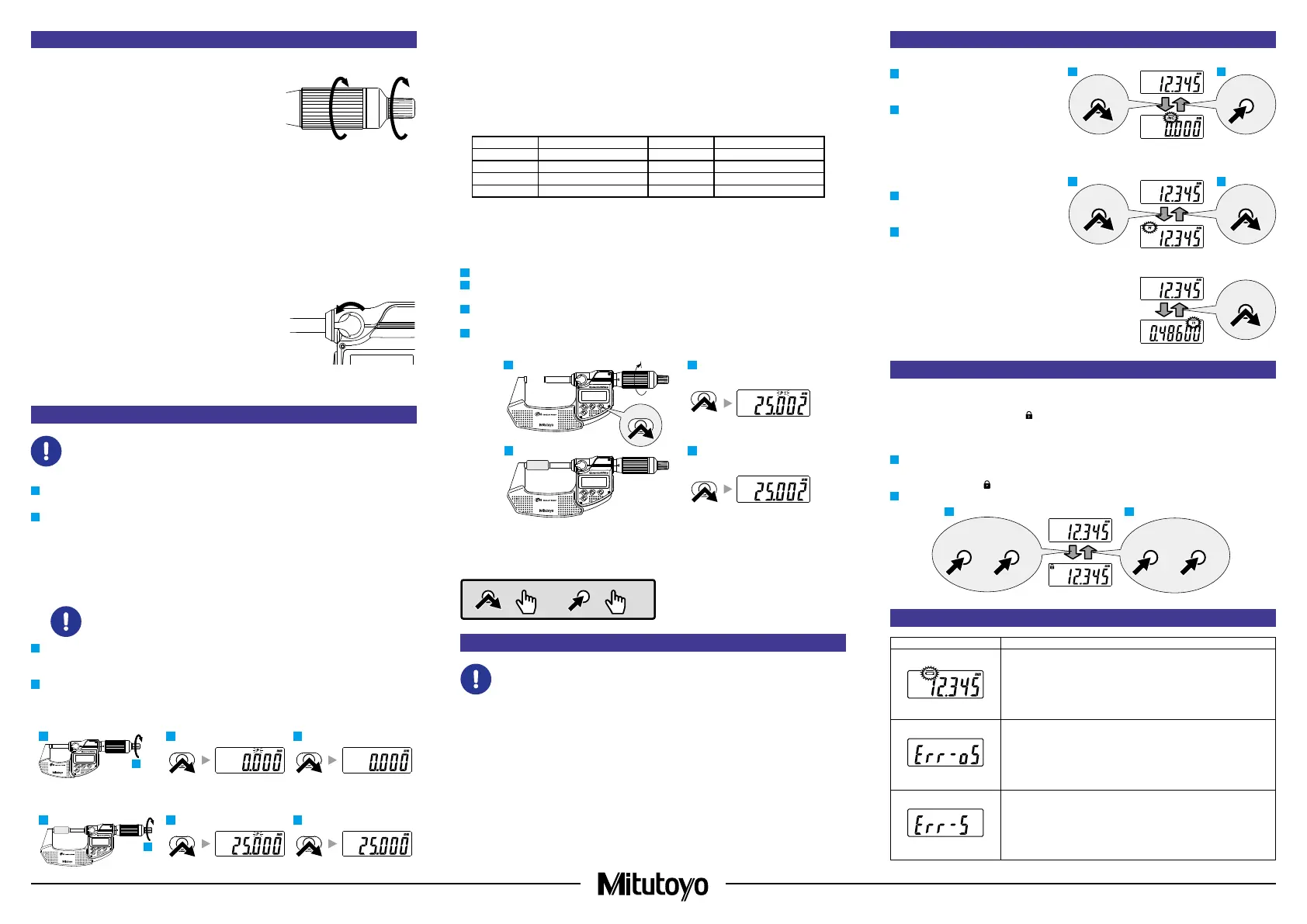
6. Key Functions
■ [ZERO/ABS] Key
1
Briefly press the [ZERO/ABS] key.
》 [INC] is displayed, and the display
is set to zero.
2
Press and hold the [ZERO/ABS] key
(for at least 2 seconds).
》 [INC] goes out, and the length from
the reference point (anvil measuring
surface) is displayed.
■ [HOLD] Key
1
Press the [HOLD] key.
》 [H] is displayed, and the display
value is held.
2
Press the key again to release the
value.
■
[in/mm] Key (in/mm Products Only)
• Press the [in/mm] key.
》 [in] and [mm] switch back and forth each time the
key is pressed.
7. Function Lock Function (Preventing Accidental Operation)
This product has the Function Lock function, which disables the ORIGIN (reference point) function
and ZERO/ABS function in order to avoid accidental changes to the reference point position.
Setting the Function Lock causes [
] on the LCD to light up and disables the [ORIGIN] key,
[ZERO/ABS] key, and [in/mm] key (in/mm products only), with only the hold operation function
enabled.
1
First press and hold the [HOLD] key, and then additionally press and hold the [ZERO/ABS] key
(for at least 2 seconds).
》 [H] display and [
] display light up in sequence ([H] turns off first).
2
Perform the same operation to release the Function Lock.
HOLD
+
ZERO/ABSHOLD
+
ZERO/ABS
21
8. Errors and Troubleshooting
Error Display Causes and Countermeasures
Power Voltage Drop
The battery voltage is low. Replace the battery promptly.
Counting Error
A counting error has occurred due to excessive speed or noise.
Try removing the battery and reinstalling.
Counting Error
Initial setting of the electrical components failed, or a counting
error has occurred due to a sensor signal error. Try removing the
battery and reinstalling.
ZERO/ABSZERO/ABS
HOLD
HOLD
in / mm
2
Rotate about three to five times.
 Loading...