EasyManua.ls Logo

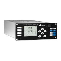
MKS Stabil-Ion 370 Series User Manual

MKS Stabil-Ion 370 Series
122 pages
To Next Page IconTo Next Page
Page #1 background imageLoading...
Page #1 background image
Series 370
Instruction Manual
Stabil-Ion
®
Vacuum Measurement Controller
Instruction manual part number 370119
Revision C - March 2020

Table of Contents

Questions and Answers:

MKS Stabil-Ion 370 Series Specifications

General IconGeneral
ManufacturerMKS Instruments
CategoryController
MountingPanel Mount
DisplayLCD
Storage Temperature-20 to 70 °C
Enclosure RatingIP20
Series370
Communication InterfaceRS-232, RS-485
AccuracyDependent on connected sensor
RepeatabilityDependent on connected sensor
Response Time<1 second

Summary

Safety

Safety Instructions

Important safety instructions and notes for installation, operation, and maintenance.

Damage Requiring Service

Conditions under which product servicing should be referred to qualified personnel.

Chapter 1 System Components

Stabil-Ion Vacuum Measuring System

Overview of the main components of the Stabil-Ion system.

Stabil-Ion Vacuum Gauge Control Unit Front Panel

Description of the main unit's front panel controls and displays.

Stabil-Ion Power Supply

Description of the Stabil-Ion Power Supply unit.

Chapter 2 Initial Setup Procedures

Control Unit Option Module Setup

Configuration of installed options on the control unit.

Power Supply Setup

Setting the line voltage and fuses for the power supply.

Chapter 3 Installation

Gauge Installation Tips

Best practices for locating and installing pressure gauges.

Stabil-Ion Gauge Installation

Steps for installing the Stabil-Ion Gauge.

Convectron Gauge Installation

Steps and safety precautions for installing Convectron gauges.

Installing the Control Unit and Power Supply

Procedures for mounting the control unit and power supply.

Grounding the System

Critical safety procedures for grounding the system.

Connecting the RS-232 Computer Interface

Instructions for connecting the RS-232 computer interface.

Connecting the RS-485 Computer Interface

Instructions for connecting the RS-485 computer interface.

Connecting the Gauge Cables

General instructions for connecting gauge cables.

Connecting the Power Cables

Final steps for connecting power cables.

Chapter 4 Preparing the Stabil-Ion System for Operation

Memory Module Loading and Operating Parameter Setup

Loading memory modules and setting operating parameters.

Control Menu Variables

Adjusting pressure range, scale factor, and gas type.

Setup Menu Variables

Adjusting units, degas time, and overpressure threshold.

Degassing the Stabil-Ion Gauge

Process and safety guidelines for degassing the gauge.

Adjustment of Convectron Gauge Zero and Atmospheric Pressure Indications

Calibrating zero and atmospheric pressure for Convectron gauges.

Chapter 5 Operation of a Stabil-Ion System

Convectron Gauge Display Formats

Explanation of different pressure display formats for Convectron gauges.

Stabil-Ion Gauge Turn ON

Basic operation for turning the Stabil-Ion Gauge ON.

Chapter 6 Theory of Operation and Specifications

Stabil-Ion Gauge Theory of Operation

Explanation of the working principles of Stabil-Ion gauges.

Stabil-Ion Gauge Specifications

Technical specifications for Stabil-Ion gauges.

Convectron Gauge Theory of Operation

Explanation of the working principles of Convectron gauges.

Convectron Gauge Specifications

Technical specifications for Convectron gauges.

Chapter 7 Service and Maintenance

Service Guidelines

General advice for servicing and contacting technical support.

Damage Requiring Service

Conditions indicating the need for professional service.

Troubleshooting the Convectron Gauge Module

Common symptoms and causes for Convectron module issues.

Troubleshooting the Electrometer Module

Troubleshooting guide for the Electrometer module.

RS-232 Troubleshooting

Common issues and solutions for RS-232 communication.

RS-485 Troubleshooting

Common issues and solutions for RS-485 communication.

Related product manuals