© MOBATIME 77 / 104 800870.05
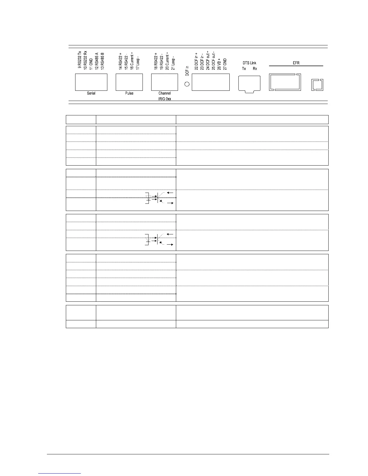
Clamp Connection Description
9 RS232 Tx
RS232 interface of line 1 (Exclusive to the RS485
interface line 1; internally the same interface)
10 RS232 Rx
11 GND
12 RS485 A
RS485 interface of line 1 (Exclusive to the RS232
interface line 1; internally the same interface)
13 RS485 B
14 RS422 + Pulse 1
RS422 output line 1 for DCF, pulse and frequency output
(internally the same source of signal like for the current
loop output)
15 RS422 – Pulse 1
16 CL + Pulse 1
Current loop line 1 for DCF, pulse and frequency output
("Current loop” passive,
optocoupler: U
max
= 50VDC, I
max
= 10mA)
17 CL – Pulse 1
18 RS422 + Digital IRIG-B signal (0xx) of the IRIG line 1
19 RS422 –
20 Current Loop +
Digital IRIG-B signal (0xx) of the IRIG line 1 as current loop
(“current loop” passive,
optocoupler: U
max
= 50VDC, I
max
= 10mA)
21 Current Loop –
22 DCF input +
DCF input e.g. for the connection of a GPS 4500 or DCF
receiver with "current loop“ output.
23 DCF input -
24 DCF output + DCF output, “current loop” passive,
U
max
= 30VDC, I
on
= 10..15mA, I
off
< 1mA @20VDC
25 DCF output -
26 DC output + DC output for GPS 4500
DC in voltage -2V, max. 400mA
27 DC output GND
DTS-Link Optical connection to a 2nd DTS 4138
Mini GBIC plug-in
EFR Option, for special applications only
 Loading...