3.7 Connecting External Devices and Sensors: MX Interface Con-
nector and MOBOTIX Cam-IO
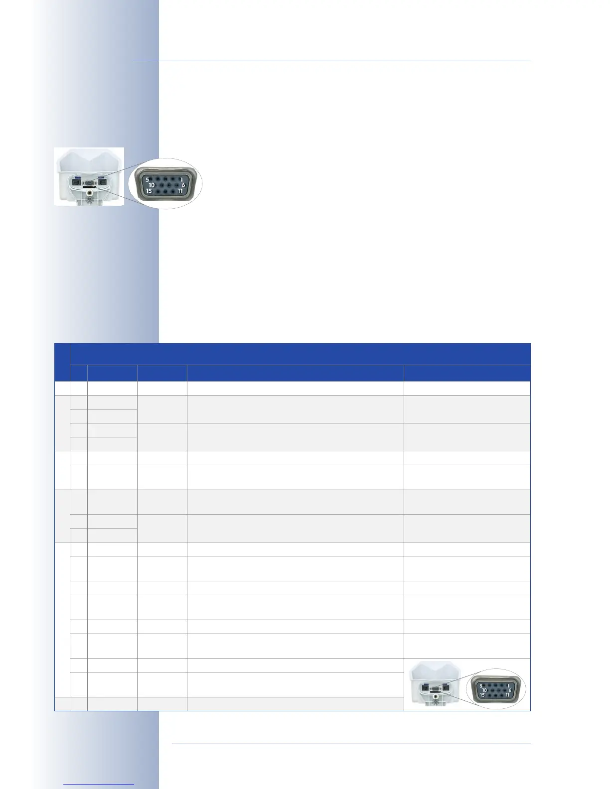
3.7.1 MX Interface Connector for Direct Connections
The MOBOTIX camera's MX Interface Connector (D Sub 15 HD) features one
signal input pin and one signal output pin for switching loads. In addi-
tion, the interface also provides two signal inputs and two signal outputs
of the RS232 interface. You can use the camera's signal input/output pins
to detect an opening door (using a Reed switch) or to switch an external de-
vice (e.g. a lamp).
The interface connector also has Line In/Out pins for external audio devices. You
can use the Line In pin to have the camera transmit and record external audio sig-
nals (e.g. from an external microphone with pre-amplifier). On the other hand, the
camera can use the Line Out pin to transmit sound to external devices (e.g. an au-
dio amplifier). This in turn opens new possibilities as the camera can feed external
loudspeakers (such as announcement systems on a train station) or it can use
external and more sensitive microphones that can be placed farther away from the
© MOBOTIX AG • Security-Vision-Systems • Made in Germany
www.mobotix.com • sales@mobotix.com
80/92
M12 Camera Manual Part 1
Pin-out of MX Interface Connector D Sub 15 HD
Pin
5
Signal
GND
udio output, Line signal level U
RMS
=1V
Galvanically isolated by
transformer (DC decoupled)
Galvanically isolated by
transformer (DC decoupled)
In/OutUSB
9
1
In 1
Out 1
13
11
USB +5V
USB D+
Serial interface
12
2
USB D-
RxD
3TxD
Signal input, active <0.5V, inactive >+3V, max. voltage 24V
Signal output, OpenCollector, active vs. GND, max. 24V/
50mA, inactive 10kOhms vs. 3.3V
Power supply for USB devices 5V/100mA vs. GND
USB master data signals, 0V to 3.3V
With backup power (12V) or PoE,
500mA also possible
RxD RS232 active = -3V to -12V, inactive +3V to +12V
RxD I/O
TxD RS232
Signal input, inactive: open or voltage >3V,
active: GND or voltage <0V, max. ±12V
active = -3V to -12V, inactive +3V to +12V
7 RTS
8 CTS
15 Backup V-In
TxD I/O
RTS RS232
Signal output, inactive: <3V max. 3mA,
active: >+3V max. 3mA, max. voltage ±12V
active = +3V to +12V, inactive -3V to -12V
RTS I/O
CTS RS232
Signal output, inactive: <3V max. 3mA,
active: >+3V max. 3mA, max. voltage ±12V
active = +3V to +12V, inactive -3V to -12V
While the system boots, the signal
state is undefined
While the system boots, the signal
state is undefined
CTS I/O Signal input, inactive: open or voltage >3V,
active: GND or voltage <0V, max. ±12V
Backup power 6V to 12V vs. GND, max. 1A